
Magnetic recording/reproducing apparatus and magnetic recording/reproducing method

a recording/reproducing apparatus and recording/reproducing technology, applied in the direction of recording signal processing, maintaining head carrier alignment, instruments, etc., can solve the problem that the recording track cannot be traced by the reproducing head upon reproduction, and the reproducing head is restricted. , to achieve the effect of ensuring a high s/n ratio of the reproduction signal, it is difficult to construct a system

Inactive Publication Date: 2007-10-18
SONY CORP
View PDF4 Cites 13 Cited by
  • Summary
  • Abstract
  • Description
  • Claims
  • Application Information

AI Technical Summary

Benefits of technology

[0016] Addressing the problems described above, the inventors of the present invention have developed a technique which can reduce the restrictions to determination of the width of the reproducing head to achieve narrowing of the track width and high density recording.
[0019] Therefore, it is demanded to provide a magnetic recording / reproducing apparatus and a magnetic recording / reproducing method which allow narrowing of the recording track width and higher density recording.
[0021] Further, it is demanded to provide a magnetic recording / reproducing apparatus and a magnetic recording / reproducing method which assure precision in tracking servo equivalent to that achieved using double-azimuth recording.
[0022] According to the present invention, there is provided a magnetic recording / reproducing apparatus comprising a recording section configured to perform a signal process for recording a signal on a magnetic recording medium, a reproducing section including a reproducing head capable of reproducing a signal from a recording track of the magnetic recording medium and configured to reproduce signals from a plurality of ones of recording tracks of the magnetic recording medium by means of the reproducing head and acquire position information of the reproducing head with respect to the plural recording tracks and then generate a reproduced signal for each of the recording tracks of the magnetic recording medium on the basis of the positional information, and an identification signal appending section provided in the recording section and configured to append an identification signal which has a recording wavelength equal to or greater than a minimum recording wavelength and causes no interference with any adjacent one of the recording tracks to a recording signal in order to allow the reproducing section to acquire the information of the reproducing head with respect to the plural recording tracks of the magnetic recording medium.
[0025] The identification signal may be recorded at a position preceding to a data region and also inside the data region such that the position information of the reproducing head with respect to the plural recording tracks is re-calculated midway of the data region. This can raise the traceability of the reproducing head with respect to the recording tracks against variation of the positional relationship between the reproducing head and the recording tracks caused by deformation of the recording medium or the like.
[0027] Data may be recorded in a plurality of groups each including a plurality of recording tracks on the magnetic recording medium such that a guard region in which recording of data is inhibited is disposed between adjacent ones of the groups. This can prevent interference between recording tracks of adjacent groups.

Problems solved by technology

However, if the width of the recording track is reduced in accordance with the traditional magnetic recording / reproducing techniques by keeping the techniques as they are, then this give rise to a problem that recording tracks cannot be traced by heads upon reproduction.
However, in order to obtain a suitable signal by adoption of the non-tracking method, there is a restriction also to setting of the reproducing head.
Therefore, where further narrowing of tracks is intended, it is difficult to construct a system which assures a high S / N ratio of the reproduction signal.
In addition, since narrowing of tracks provides a limitation at which the azimuth cannot be used any more, it is difficult to use the conventional methods.

Method used


Image

  • Magnetic recording/reproducing apparatus and magnetic recording/reproducing method
  • Magnetic recording/reproducing apparatus and magnetic recording/reproducing method
  • Magnetic recording/reproducing apparatus and magnetic recording/reproducing method

Examples


first embodiment

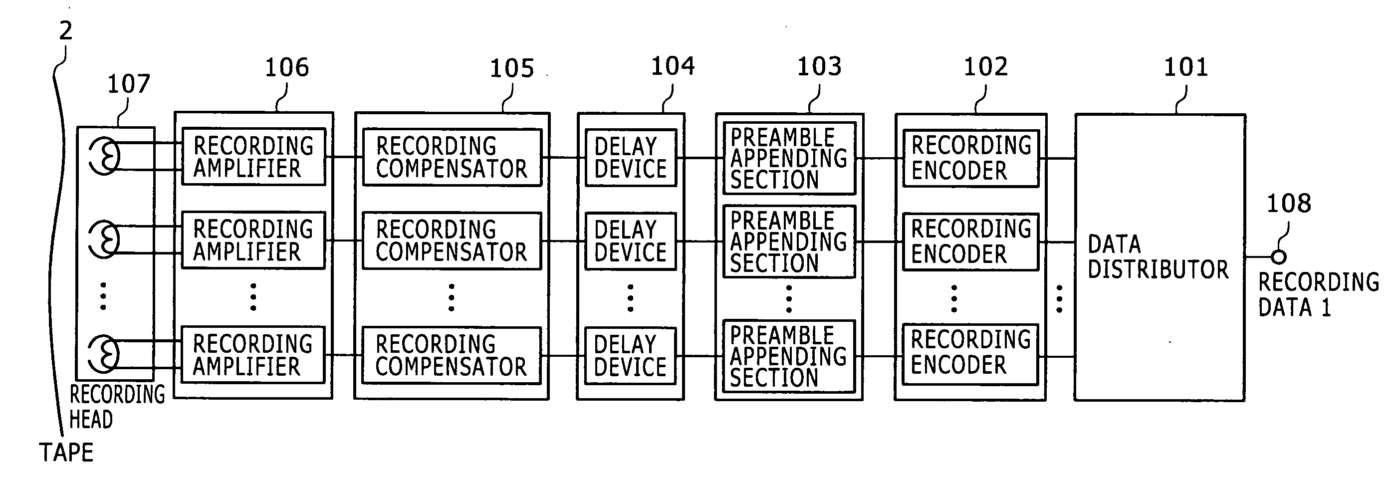
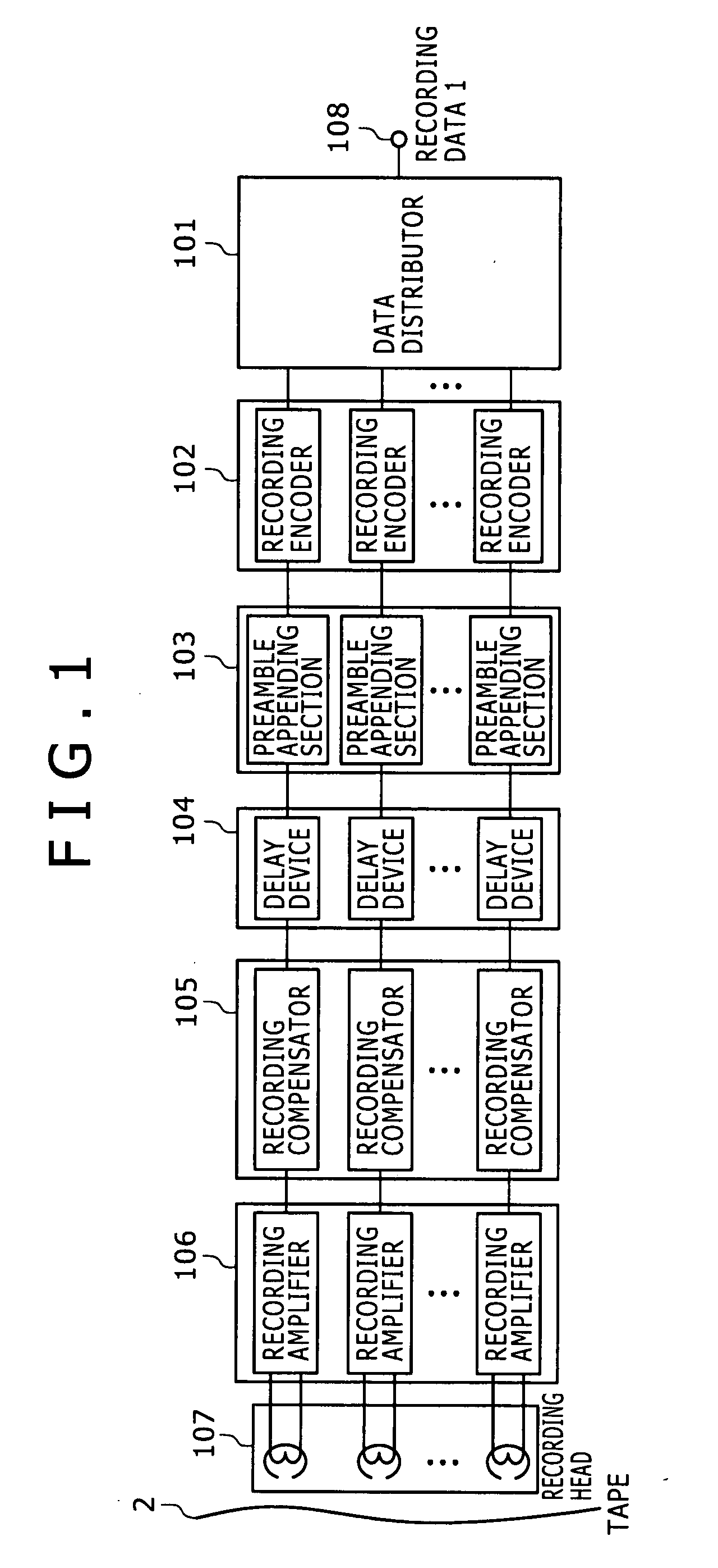
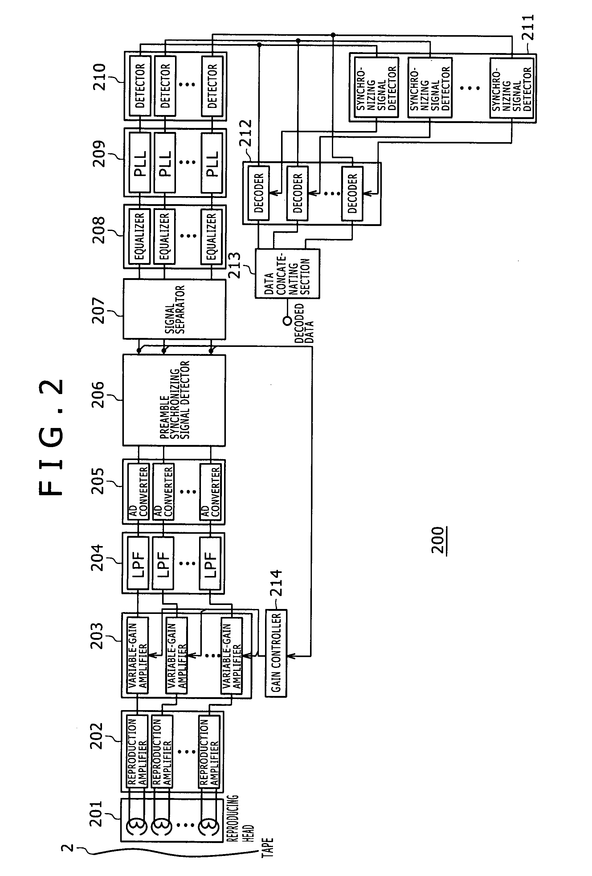
[0048]FIG. 1 shows the configuration of a recording apparatus of a magnetic recording / reproducing apparatus according to a first embodiment of the present invention which makes use of multi-head arrays, and FIG. 2 shows the configuration of a reproducing apparatus of the magnetic recording / reproducing apparatus. It is to be noted that the number of recording heads of the recording heady array is M whereas the number of reproducing heads of the reproducing head array is N.

[0049] First of all, the configuration of the recording apparatus 100 is described with reference to FIG. 1.

[0050] The recording apparatus 100 includes a data distributor 101, M recording encoders 102, M preamble appending sections 103, M delay devices 104, M recording compensators 105, M recording amplifiers 106 and M recording heads 107.

[0051] The data distributor 101 distributes recording data 1 inputted thereto from a terminal 108 to M groups of data equal to the number of the recording heads 107 in accordanc...

second embodiment

[0122] Now, a magnetic recording / reproducing apparatus according to a second embodiment of the present invention which employs a single recording head and a single reproducing head is described with reference to FIGS. 12 to 15.

[0123]FIG. 12 shows the configuration of a recording apparatus of the magnetic recording / reproducing apparatus according to the present embodiment, and FIG. 13 shows the configuration of a reproducing apparatus of the magnetic recording / reproducing apparatus.

[0124] Referring first to FIG. 12, the recording apparatus 300 includes a data distributor 101, M recording encoders 102, and M preamble appending sections 103 similarly as in the recording apparatus 100 described hereinabove with reference to FIG. 1. However, the recording apparatus 300 is different from the recording apparatus 100 in that it includes a single delay device 104, a single recording compensator 105, a single recording amplifier 106 and a single recording head 107. The recording apparatus 3...

third embodiment

[0135] The present invention can be applied not only to the magnetic recording / reproducing system conforming to the non-azimuth method, but also to a magnetic recording / reproducing system conforming to the double-azimuth method.

[0136]FIG. 16 illustrates a method of recording data on the magnetic recording medium 2 in conformity with the double-azimuth method.

[0137] Also in the present method, the recording track number M is 4 (M=4) similarly as in the method described hereinabove with reference to FIG. 5. In particular, four data frames 3 are recorded on the magnetic recording medium 2 and are handled as one group in a reproduction signal process. The data frames 3 of each group are recorded such that the azimuth angle thereof is different from that of the data frames 3 of an adjacent group. By carrying out azimuth recording on the magnetic recording medium 2, it is possible to prevent interference between recording tracks belonging to adjacent groups. Thus, it is not necessary to...


PUM


Abstract

A magnetic recording / reproducing apparatus is disclosed wherein reproduced signals read out from a plurality of recording tracks using a reproducing head can be separated into original recording signals of the recording tracks. Upon recording, an identification signal which has a recording wavelength equal to or greater than a minimum recording wavelength and causes no interference of any of the recording tracks with any adjacent one of the recording tracks is appended to and recorded together with a recording signal in order to allow, upon reproduction, acquisition of the position information of the reproducing head with respect to the plural recording tracks of the magnetic recording medium. Upon reproduction, a reproduced signal for each of the recording tracks of the magnetic recording medium is generated on the basis of the positional information read from the recording tracks.

Description

CROSS REFERENCES TO RELATED APPLICATIONS [0001] The present invention contains subject matter related to Japanese Patent Application JP 2006-103065, filed in the Japan Patent Office on Apr. 4, 2006, the entire contents of which being incorporated herein by reference. BACKGROUND OF THE INVENTION [0002] 1. Field of the Invention [0003] The present invention relates to a magnetic recording / reproducing apparatus for recording data on a magnetic recording medium by making use of a recording head or a plurality of recording heads and reproducing signals from a plurality of tracks of the magnetic recording medium by making use of a reproducing head or a plurality of reproducing heads as well as relates to a magnetic recording / reproducing method adopted by the magnetic recording / reproducing apparatus. [0004] 2. Description of the Related Art [0005] In recent years, it has been and is being demanded for a magnetic recording / reproducing apparatus to achieve higher density recording in order t...

Claims


Application Information

Patent Timeline
IPC IPC(8): G11B20/10
CPCG11B5/588G11B20/10009G11B2220/90G11B27/3018G11B20/22
Inventor HIURA, TOMOYUKIINO, HIROYUKINAKAGAWA, TOSHIYUKIMIHOTA, NORIHITOIKEGAMI, TOMOHIROFUKUDA, SHINICHIDEOKA, YOSHIHIKOHONDA, HIDETOSHIHARA, MASAAKI
Owner SONY CORP
Learn More