
Differential amplifier, digital-to-analog converter and display device

a technology of digital to analog converter and display device, which is applied in the direction of differential amplifier, amplifier with semiconductor device/discharge tube, amplifier details, etc., can solve the problems of increasing die cost, limitation of offset suppressing effect, and document 1, 2 and 3

Inactive Publication Date: 2007-10-11
NEC CORP
View PDF6 Cites 17 Cited by
  • Summary
  • Abstract
  • Description
  • Claims
  • Application Information

AI Technical Summary

Benefits of technology

The present invention provides a multi-level-output differential amplifier, digital-to-analog converter, and display device that make possible a reduction in decoder area and a high-precision output. The invention solves the problem of increased die cost resulting from the greater number of gray levels by requiring a smaller number of gray scale voltage lines and transistors for selecting the gray levels. The invention also addresses the issue of offset suppressioning in the case of a TFT circuit configuration by using a capacitance element. The invention provides a method for time-averaging offset over a plurality of frames to achieve a high-precision output.

Problems solved by technology

This leads to an increase in die cost, which constitutes a first problem of the conventional art.
This is a second problem of the conventional art.
With respect to the demand for a high-precision output, the method of time-averaging offset over a plurality of frames described in Patent Document 1 is such that in the case of the above-mentioned TFT circuit configuration, for example, the absolute value of the offset per se is large and, hence, there is a limitation upon the offset suppressing effect.
However, none of the inventions of Patent Documents 1, 2 and 3 solve the first problem of the conventional art, namely the increase in die cost resulting from the greater number of gray levels.

Method used


Image

  • Differential amplifier, digital-to-analog converter and display device
  • Differential amplifier, digital-to-analog converter and display device
  • Differential amplifier, digital-to-analog converter and display device

Examples


first example

THIRD MODIFICATION OF FIRST EXAMPLE

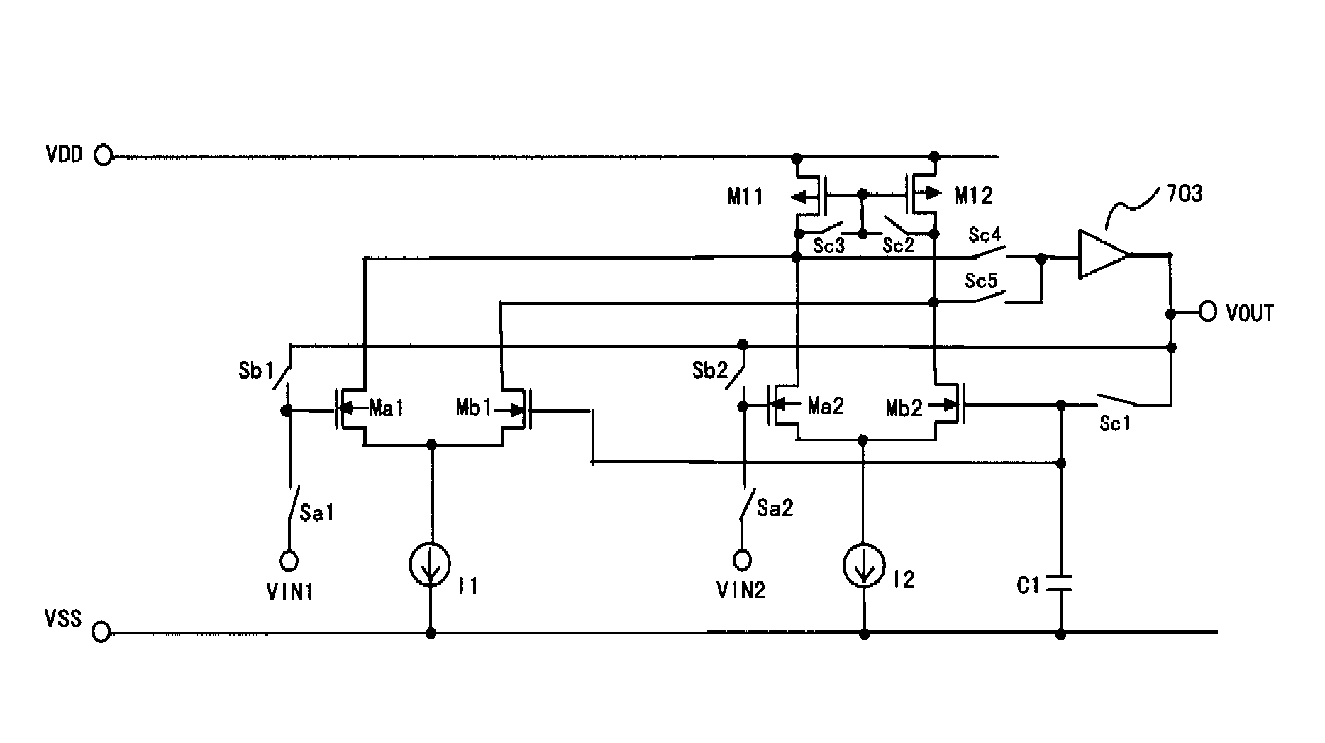
[0288]A further modification of this example will now be described. In this modification, an internally divided voltage can be generated and output with high precision at an internal dividing ratio other than (1:2). In the third modification, in which use is made of a circuit configuration identical with that of FIG. 9 (the first example), the transistor sizes and the current values of the current sources are set as indicated below. The ratio of the gate widths Wa1, Wb1, Wa2 and Wb2 of transistors Ma1, Mb1, Ma2 and Mb2, respectively, of the two differential pairs and the current ratio of the current sources I1 and I2 are set as indicated below. Switch control is similar to that shown in FIG. 10.

Wa1:Wb1:Wa2:Wb2=a2:a2:b2:b2   (37)

I1:I2=1:1   (38)

[0289]The following Equations (39) to (44) hold in period T01:

Ia1=Ib2(39)Ib1=Ia2(40)Ia1=12×a2βn{(Vin1-VS1)-Vthna1}2(41)Ib1=12×a2βn{(Vout-VS1)-Vthnb1}2(42)Ia2=12×b2βn{(Vin2-VS2)-Vthna2}2(43)Ib2=12×b2βn{(Vout-V...

second example

[0306]A second example of the present invention will be described with reference to the accompanying drawings in regard to implementation of a multi-level-output in a case where three input voltages are applied.

[0307]The circuit configuration of the second example of the present invention will now be described. FIG. 20 is a diagram illustrating the configuration of a differential amplifier according to the second example. The differential amplifier according to this example comprises: first differential pair (Ma1, Mb1) driven by current source 11; second differential pair (Ma2, Mb2) driven by current source 12; third differential pair (Ma3, Mb3) driven by current source 13; current mirror load circuit (M11, M12) to which the output pairs of the differential pairs are connected in common; and output-stage amplifying circuit 703.

[0308]Input terminal VIN1 is connected to the gate of one transistor Ma1 of the differential inputs of the first differential pair via switch Sa1, and the out...

third example

[0317]The circuit configuration of a third example of the present invention will now be described. FIG. 23 is a diagram showing the configuration of a differential amplifier according to the third example. For example, the differential amplifier shown in FIG. 23 employs the differential amplifier (FIG. 9) shown in the first example of the present invention. In the third example, the amplifier is further provided with an output switch SWout.

[0318]Switch control of the differential amplifier shown in FIG. 9 is carried out at the timing shown in FIG. 10. The output switch SWout in the third example is set in an OFF state in the offset detection period T01 and in an ON state in the offset-compensated output period T02.

[0319]By using the third example of FIG. 23, the amplifier stage output PB of the differential amplifier is cut off from an external (not shown) such as a data line in the offset detection period T01. As a result, the load is essentially the capacitor C1 for detecting offs...


PUM


Abstract

Disclosed are a multi-level differential amplifier that includes first to third input terminals; an output terminal; first to third differential pairs; a current source circuit for supplying currents to the respective first to mth differential pairs; a load circuit connected to first and second nodes to which first and second outputs of each of output pairs of the first to third differential pairs are connected in common; an amplifier stage receiving a signal from at least one node of the first and second nodes as an input and having its output connected to the output terminal; and a capacitance element. A data output period includes first and second periods. In the first period, responsive to a control signal, a first input of each input pair of the first to third differential pairs is made a non-inverting input, the second input is made an inverting input, the first inputs are connected to the respective first to third input terminals, and the second inputs of the first to third differential pairs are connected in common with one end of the capacitance element and with the output terminal. In the second period, responsive to a control signal, the first input of each input pair of the first to third differential pairs is made an inverting input and the second input is made a non-inverting input, the first inputs of each of the input pairs are connected in common with the output terminal, and the second inputs are connected in common with the one end of the capacitance element.

Description

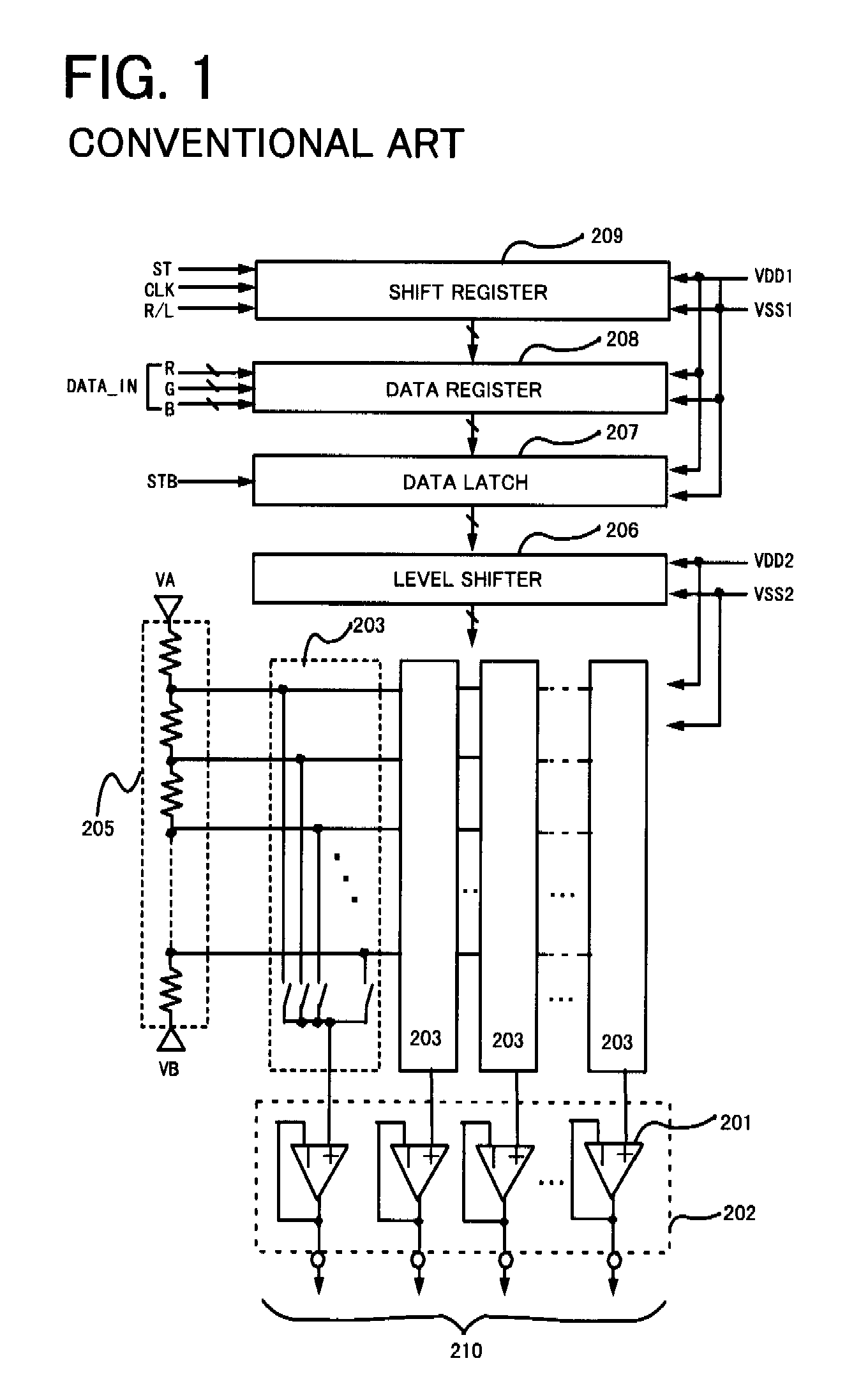
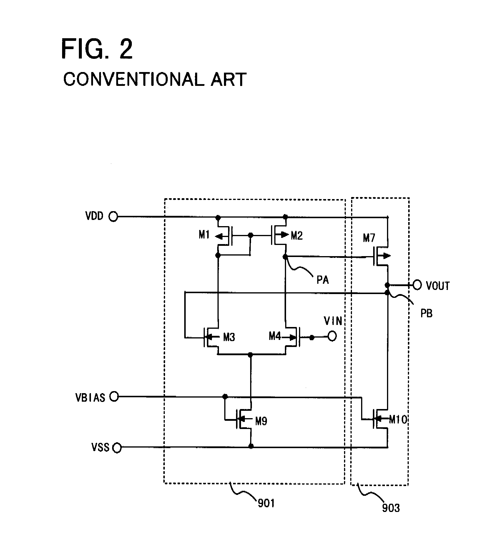
FIELD OF THE INVENTION[0001]This invention relates to a differential amplifier, digital-to-analog converter and display device. More particularly, the invention relates to a multi-level-output differential amplifier that is ideal for offset cancellation.BACKGROUND OF THE INVENTION[0002]A configuration of the kind illustrated in FIG. 1 is in use as a data driver for driving the data lines of a liquid crystal display device. Referring to FIG. 1, this conventional data driver includes a shift register 209, data register 208, data latch 207, level shifter 206, grayscale voltage generating circuit 205, decoders 203 and output circuit 202 (amplifiers 201).[0003]The operation of the conventional data driver shown in FIG. 1 will now be described. The shift register 209 outputs shift pulses responsive to a clock signal CLK, and the data register 208 successively up-shifts input video data DATA_IN responsive to the shift pulses from the shift register 209 and delivers the video data in accord...

Claims


Application Information

Patent Timeline
Patent Type & Authority Applications(United States)
IPC IPC(8): H03F3/45
CPCH03F3/45179H03F3/45744H03F3/45748H03F2203/45212H03M1/0607H03F2203/45588H03F2203/45616H03F2203/45681H03F2203/45726H03F2203/45536
Inventor IRIGUCHI, MASAO
Owner NEC CORP
Learn More