Motor Drive Circuit, Motor System, and Motor Drive Method

a technology of motor drive and motor system, which is applied in the direction of motor/generator/converter stopper, electronic commutator, dynamo-electric converter control, etc., can solve the problems of difficult setting the optimum constant, large number of parts, and inability to use a microprocessor, etc., to achieve the smallest chip size, stable rotation operation of the motor, and the effect of reducing the size of the ic circui

Inactive Publication Date: 2007-10-11
SONY CORP
View PDF5 Cites 9 Cited by
  • Summary
  • Abstract
  • Description
  • Claims
  • Application Information

AI Technical Summary

Benefits of technology

[0033] According to the present invention, it is possible to obtain a circuit more suitable for formation as an IC in comparison with a conventional circuit, able to minimize the size of the IC circuit, decreasing the number of externally attached electric parts other than the IC, making the constants of the externally attached electric parts values giving the smallest chip size, and obtaining further stable rotation operation of the motor.

Problems solved by technology

Further, the drive circuit of a general sensorless motor prepares for a case where the rotor of the motor is already at a location where it should stop (also referred to as the “reference position”) and therefore the rotor of the motor is not started up immediately after the supply of power to the drive coils of the three phases by generating a startup pulse and forcibly switching to a power supply pattern of the drive coils of three phases when it is not possible to detect the induction voltage in the drive coils of the three phases within a certain time.
Accordingly, a system having a large circuit scale can use the digital system, but applications where the circuit must be made small in scale cannot use a microprocessor etc. due to costs and the mounting area.
The analog system has the defects that it is necessary to set the optimum constant of each element of the CR time constant circuit, but the setting the optimum constant is difficult since there are constant values which interfere with each other between elements.
Further, large numbers of resistors and capacitors are necessary, therefore the number of parts becomes large.
The motor generally used at the present is a brush-type coreless motor, but this motor has the problem of a short service life due to wear of the brush and the problem that the outside dimensions are hard to reduced in the diameter direction due to the structural requirement that air gaps must be provided inside and outside the rotating coil.

Method used


Image

  • Motor Drive Circuit, Motor System, and Motor Drive Method
  • Motor Drive Circuit, Motor System, and Motor Drive Method
  • Motor Drive Circuit, Motor System, and Motor Drive Method

Examples


Embodiment Construction

[0048] Below, an embodiment of the present invention will be explained with reference to the drawings.

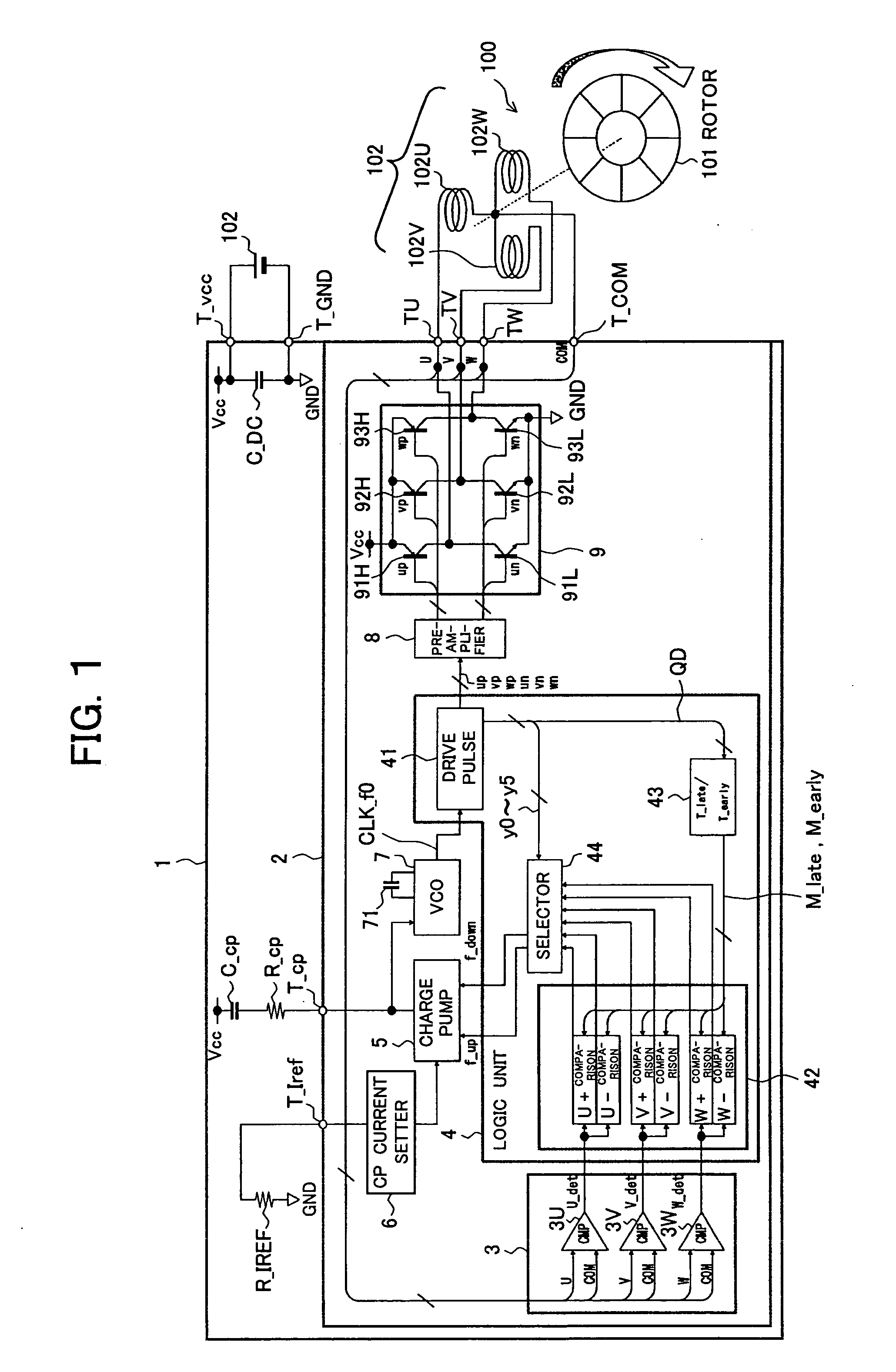
[0049]FIG. 1 shows a sensorless three-phase brushless DC motor according to an embodiment of the present invention and a motor drive circuit thereof.

[0050] A motor drive circuit 1 exemplified in FIG. 1 drives a sensorless three-phase brushless DC motor (hereinafter simply referred to as a “motor”) 100. The motor 100 has a built-in rotor 101 provided with a magnet and stator provided with motor drive coils 102U, 102V, and 102W (hereinafter simply referred to as “coils 102”) of for example three phases (U-phase, V-phase, and W-phase).

[0051] The shaft of the rotor 101 is provided around it with for example eight magnets.

[0052] The coils 102 are comprised of three coils arranged facing the rotor 101 with an electrical phase difference of 120°, i.e., a U-phase coil 102U, a V-phase coil 102V, and a W-phase coil 102W.

[0053] These three coils are connected in a star configuration. A co...


PUM


Abstract

A circuit suitable for formation as a small sized IC, able to decrease the number of externally attached parts and reduce the size, and stably rotating a motor. When rotating a rotor 101 by three-phase drive signals U, V, and W generated based on a CLK signal from a VCO 7, induction voltages induced in the three-phase coils 102 are monitored and a phase deviation of a rotor phase relative to an electric phase is detected. As a result, when the rotor phase is late relative to the electric phase, a charge pump circuit 5 is driven by an up signal f_up which becomes active for exactly a time in accordance with the phase delay amount, while when the rotor phase is advanced, the charge pump circuit 5 is driven by a down signal f_down which becomes active for exactly a time corresponding to a phase advance amount. In this motor drive circuit 1, the voltage of a VCO control terminal T_cp is directly and instantaneously and dynamically changed not in accordance with detected phase deviation information without going through a smoothing filter.

Description

TECHNICAL FIELD [0001] The present invention relates to a drive circuit of a so-called sensorless type brushless motor not having a position detection sensor for detecting a rotation angle of a rotor, a motor system including this, and a motor drive method. BACKGROUND ART [0002] As a drive circuit of sensorless motor, for example a circuit driving a three-phase brushless motor is known. [0003] This circuit for driving a three-phase brushless motor does not use a Hall element or other circuit detection element, but utilizes an induction voltage (inverse electromotive force or EMF (electromotive force)) generated in the drive coils of the three phases and switches the drive current supplied to the drive coils of the three phases. The drive circuit of this type of general sensorless motor detects the induction voltage of the excitation coils of the three phases, gives a certain delay amount to a timing when a polarity is inverted, and switches application of the drive current supplied ...

Claims


Application Information

Patent Timeline
Patent Type & Authority Applications(United States)
IPC IPC(8): H02P3/18H02P23/00H02P6/06H02P6/08H02P6/15
CPCH02P23/0081H02P23/0068H02P23/22H02P23/26
Inventor SUZUKI, MASAHIRO
Owner SONY CORP
Why Eureka
Try Eureka