
Apparatus for Processing Highly Corrosive Agents

Inactive Publication Date: 2007-10-11
CASALE SA
View PDF9 Cites 8 Cited by
  • Summary
  • Abstract
  • Description
  • Claims
  • Application Information

AI Technical Summary

Benefits of technology

[0024] Moreover, thanks to the particular compatibility between these two metals and their similar chemical / physical properties, it is possible to firmly and long-lastingly bond the zirconium coating with the titanium tube. All of this using simple and conventional realization techniques and without the two metals, during the operation of the apparatus, tending to disbond or in any case coming under tension one with respect to the other, thus keeping the structural and anti-corrosive resistance of such materials unchanged through time and avoiding any type of laceration or crack of the coating layer.

Problems solved by technology

Added to this, as well as such critical operative conditions, the process fluid often also exerts a corrosive and / or erosive action on the surfaces with which it comes into contact due, in particular, to the presence of highly corrosive agents.
These substances exert an aggressive consumption and erosion action of the inner surfaces of such tubes with which they come into contact.
It follows from this that such apparatuses are seriously damaged already after short periods of operation, in some cases even after a few months of activity.
This means having to shut down the whole urea production plant for their repair, but more frequently replacement with new apparatuses, with clear negative effects in terms of loss of production and maintenance costs.
Moreover, frequent stopping and restarting of the plant can cause damage to the other apparatuses or their rapid wear, as well as additional energy consumption.
However, despite the recognized effectiveness of zirconium coating against the chemical corrosion determined by the aforementioned agents, this type of apparatuses does not allow completely satisfactory results to be achieved.
The process fluid thus manages to infiltrate into such “critical” zones and, since the steel tube is without protection, it is therefore thus subject to the corrosive attack of such a fluid, with consequent rapid and serious damage to the heat exchange apparatus.
It follows from this that, as well as being difficult to carry out due to the objective difficulty in realizing a zirconium coating on steel tube bundles, current heat exchangers of the type considered here are very onerous from the point of view of maintenance, requiring frequent checks and frequent repair interventions.

Method used


Image

  • Apparatus for Processing Highly Corrosive Agents
  • Apparatus for Processing Highly Corrosive Agents

Examples


Embodiment Construction

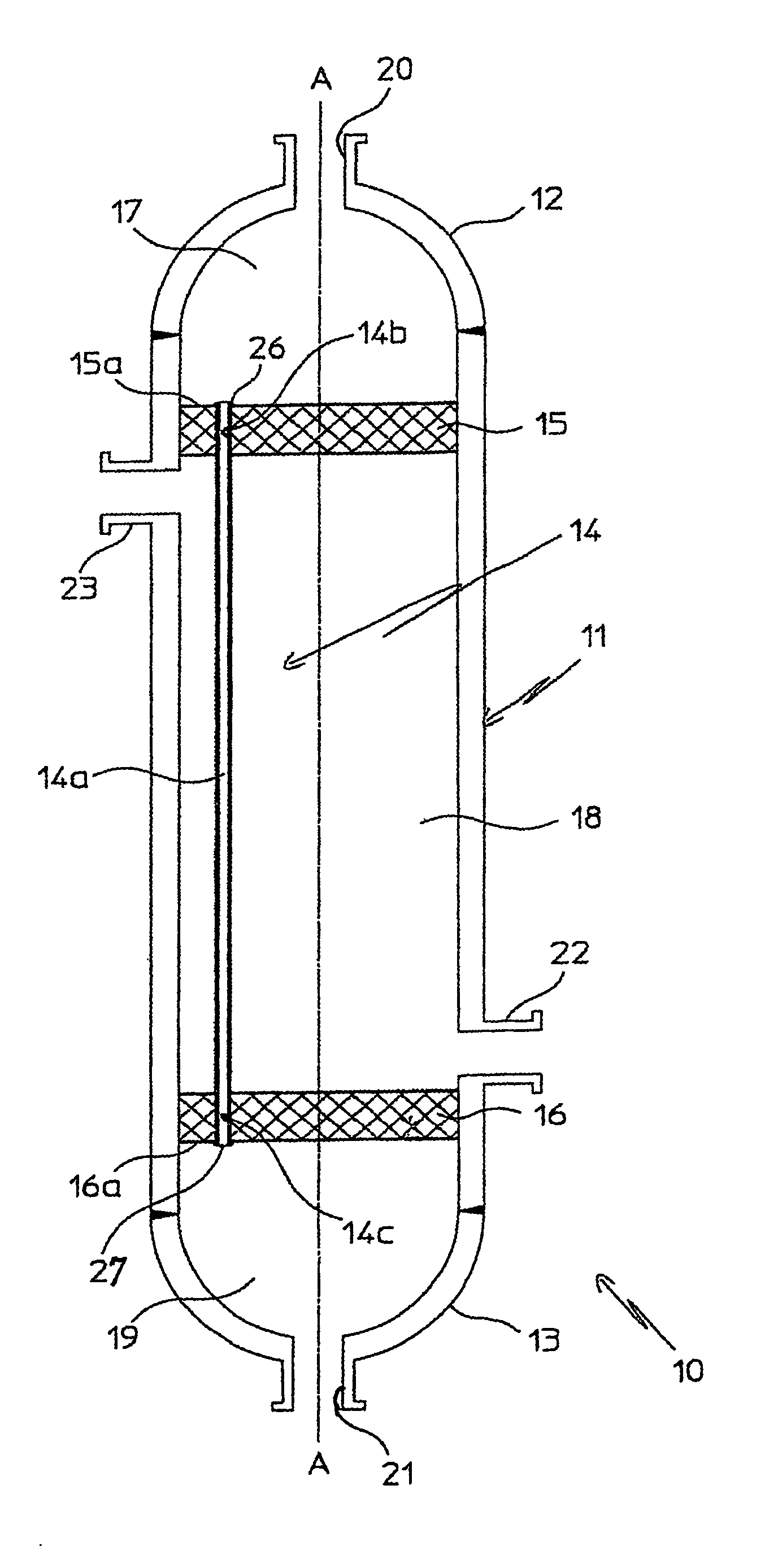
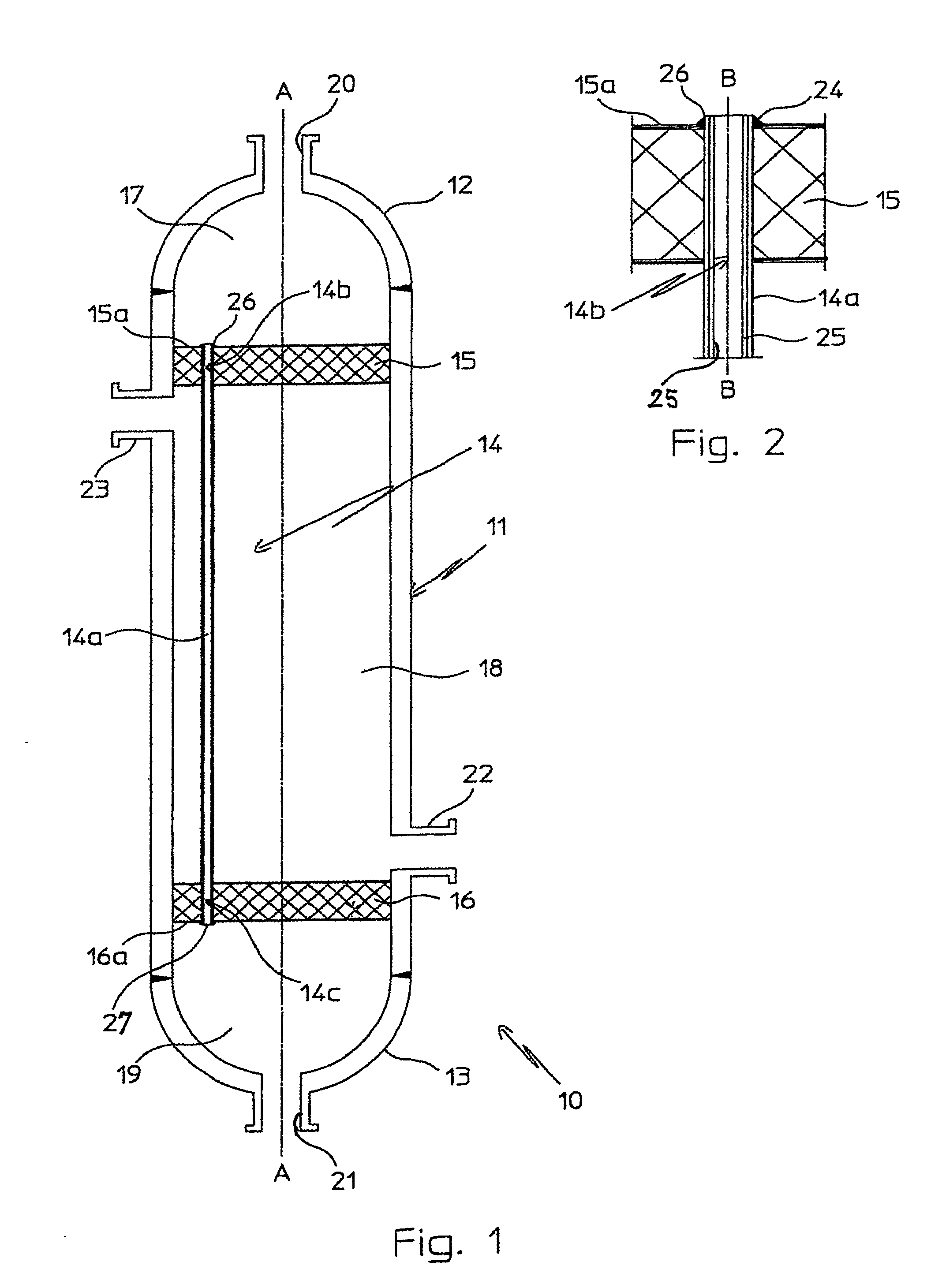
[0029] With reference to the aforementioned figures, the heat exchange apparatus according to the invention shall be described, purely for indicating and not limiting purposes, with specific reference to a descending film tube bundle heat exchanger 10, with vertical tubes, that has advantageous and specific use as a stripper of a urea production plant, but it is clear that it can be used as a condenser, evaporator, boiler, reactor or similar apparatuses based upon the heat exchange between two fluids.

[0030] In particular, the heat exchanger 10 according to the invention has advantageous and specific use as a stripper or condenser in a high pressure synthesis section of an urea plant, and more precisely of a urea plant of so-called CO2 or ammonia stripping, not represented because it is conventional. Such a section generally comprises at least one synthesis reactor, a stripper for the decomposition of the ammonium carbamate and of the-free ammonia present in the reaction mixture com...


PUM

PropertyMeasurementUnit
Fractionaaaaaaaaaa
Fractionaaaaaaaaaa
Thicknessaaaaaaaaaa

Abstract

An apparatus for treating highly corrosive agents comprises a tube bundle (14) heat exchanger (10), structured to carry out a heat exchange between two fluids one of which is highly corrosive and flowing inside of said tube bundle (14).

Description

FIELD OF APPLICATION [0001] The present invention, in its most general aspect, refers to apparatuses intended for treating highly corrosive chemical agents, with respect to which a specialized, effective and long-lasting protection is required. [0002] In particular, this invention concerns an apparatus of the aforementioned type, in which the treating of corrosive agents is substantially a heat-treating. [0003] Yet more specifically, the present invention refers to an apparatus of the type considered, comprising or essentially consisting of a tube bundle heat exchanger, structured to carry out a heat exchange between two fluids one of which is highly corrosive. [0004] Heat exchange apparatuses falling within the scope of protection of the present invention are, for example, synthesis, decomposition, condensation or evaporation reactors, stripping apparatuses, boilers, concentrators and similar devices that require the heat exchange between a process fluid and an operating fluid. [00...

Claims


Application Information

Patent Timeline
IPC IPC(8): F28F19/06C01B21/12C01C1/04F28F21/08
CPCF28F21/086F28F19/06B01J12/02B01J14/00F28D7/1623F28F2275/06
Inventor ROMITI, DOMENICO
Owner CASALE SA
Learn More