
Probe, image diagnostic system and catheter

a technology of image diagnostic system and probe, which is applied in the field of probe, image diagnostic system and catheter, can solve the problems of not being suitable, affecting the operation of the drive shaft,

Inactive Publication Date: 2007-10-04
TERUMO KK
View PDF8 Cites 103 Cited by
  • Summary
  • Abstract
  • Description
  • Claims
  • Application Information

AI Technical Summary

Benefits of technology

[0013]According to one aspect, an image diagnostic system comprises a probe positionable in a body cavity and configured to repeatedly transmit signals and acquire signals reflected from biotissue surrounding the body cavity during radial scanning, a scanner and pullback unit connected to the probe to rotate and axially move the probe during the radial scanning, and a torque limiter positioned to limit a torque load applied to the probe by the scanner and pullback unit, with the torque limiter comprising a shaft portion provided with a plurality of circumferentially arranged grooves which cause the shaft portion to break when the torque load applied by the scanner and pullback unit exceeds a predetermined load. In addition, a control unit is connected to the probe by way of a transmission line to produce digital data based on the acquired signals and to construct a tomographic image of the body cavity and the biotissue surrounding the body cavity on the basis of the digital data, and a display unit is connected to the control unit to display the tomographic image.
[0014]According to another aspect, an image diagnostic system comprises a probe positionable in a body cavity and configured to repeatedly transmit signals and acquire signals reflected from biotissue surrounding the body cavity during radial scanning, a control unit connected to the probe to produce digital data based on the acquired signals and to construct a tomographic image of the body cavity and the biotissue surrounding the body cavity on the basis of the digital data, and a display unit configured to display the tomographic image. The probe comprises a shaft transmitting a rotational drive force during the radial scanning by the probe, and a transmission line extending along the shaft to transmit the reflected signals to the control unit, with the shaft receiving the rotational drive force via a torque limiter. The torque limiter possesses a thickness which is non-uniform in a circumferential direction of the torque limiter at a part along a length of the torque limiter.
[0015]Another aspect involves a probe connectable to an image diagnostic apparatus and positionable in a body cavity, wherein the probe comprises an imaging core for transmitting signals and receiving reflected signals used by the image diagnostic apparatus to produce digital data for constructing a tomographic image of the body cavity and biotissue surrounding the body cavity, wherein the image core comprises a shaft configured to transmit rotational drive force to a distal portion of the imaging core, a transmission line extending along the shaft to transmit the reflected signals to the control unit, and a torque limiter positioned at a portion of the shaft to limit a torque load transmitted to the distal portion of the imaging core. The torque limiter possesses a thickness which is non-uniform in a circumferential direction of the torque limiter at a part along a length of the torque limiter.
[0016]In accordance with another aspect, a catheter comprises a sheath possessing a lumen, a shaft positioned in the lumen and configured to transmit a rotational drive force to a distal portion, and a torque limiter positioned at a proximal portion of the shaft to transmit the rotational drive force when the rotational drive force is less than a predetermined value, the torque limiter possessing a vulnerable portion along a circumferential direction that breaks upon application of a load torque equal to or greater than the predetermined value to prevent transmission of the torque load equal to or greater than the predetermined value to the distal portion.
[0017]With the system, probe and catheter disclosed herein, once an overload is applied to a distal end portion of a driveshaft, the drive is instantaneously and reliably cut off rotational drive force from the driveshaft.

Problems solved by technology

Such a driveshaft presents a potential problem in that an overload may be applied to the distal end portion of the driveshaft if a catheter (i.e., probe) is trapped at a constricted point or an exterior sheath covering the driveshaft is damaged when the catheter is inserted into a body cavity such as a blood vessel or lumen.
This system thus involves a potential risk that damage to a blood vessel or lumen may occur from the time an overload is applied to the driveshaft until the motor comes to a full stop.
In addition, this construction relies upon an electrical cut-off and hence, is not well suited to eliminating the potential risk of an inadvertent actuation and is considered to have low reliability in stopping rotational drive.
On the other hand, the system described in JP-A-10-66696 that controls the drive torque of the rotational drive source by magnetic force and centrifugal force also involves a potential risk that damage to a blood vessel or lumen may increase because if an applied torque becomes smaller for one reason or another subsequent to the application of an overload to a driveshaft, the rotational drive source may be connected again to the rotational drive section to transmit drive force to the rotational drive section.

Method used


Image

  • Probe, image diagnostic system and catheter
  • Probe, image diagnostic system and catheter
  • Probe, image diagnostic system and catheter

Examples


first embodiment

1. General Overall Construction of IVUS Imaging System

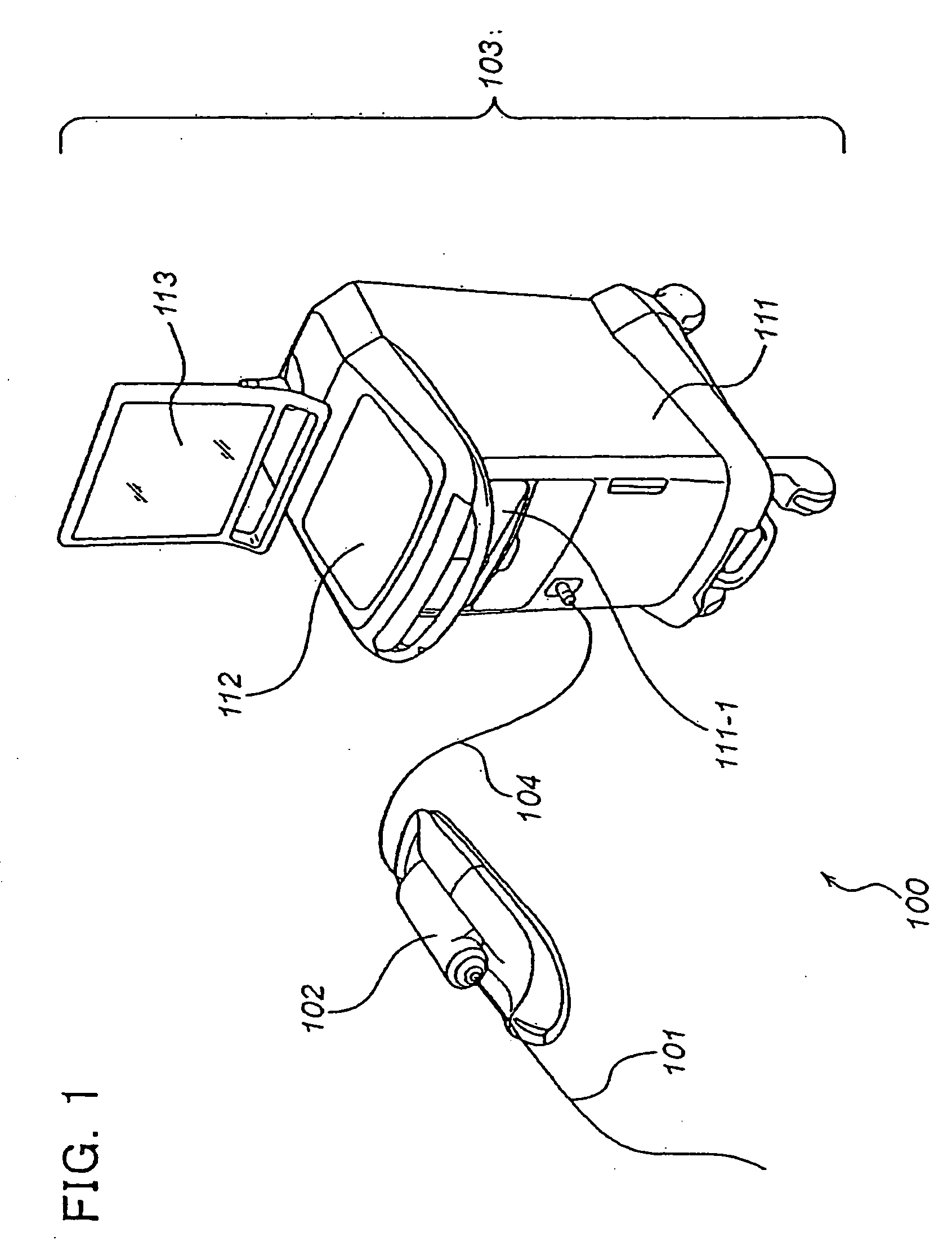
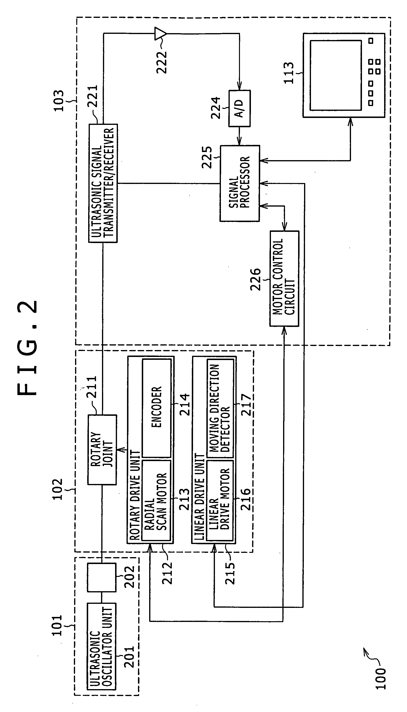
[0043]Referring to FIG. 1, an intravascular ultrasound (IVUS) imaging system (i.e., image diagnostic system) 100 according to one illustrated and disclosed embodiment includes a catheter section (i.e., probe) 101, a scanner & pull-back unit 102 and an operation control system 103. The scanner & pull-back unit 102 and the operation control system 103 are connected together via a signal line 104 and compose an image diagnostic apparatus.

[0044]The catheter section 101 is adapted to be inserted directly into a blood vessel to measure internal conditions of the blood vessel by way of an ultrasonic transducer 701b which is shown in FIG. 7. The scanner & pull-back unit 102 controls movements of the ultrasonic transducer 701b within the catheter section 101.

[0045]The operation control system 103 operates to input various preset values upon performing an intravascular ultrasound diagnosis and to also process data acquired by a measurement...

second embodiment

[0103]The description above describes the probe (catheter section) in the IVUS imaging system. However, the disclosure here is not specifically limited to IVUS imaging systems, but rather has useful application to other image diagnostic systems. The following describes application of the disclosure here to probes of an optical coherence tomography (OCT) imaging system and an OCT imaging system making use of a wavelength swept light source as a modification of the first-mentioned OCT imaging system.

1. Measurement Principle of OCT Imaging System

[0104]The measurement principle of an OCT imaging system will first be briefly described. Because light is electromagnetic radiation, it generally has the property that beams of light interfere with each other when they are superimposed. The interference property that defines whether light interferes readily or hardly is called “coherence”, and in general OCT imaging systems, low-coherence light of low interference property is used.

[0105]When t...


PUM


Abstract

A probe which is adapted to repeatedly transmit and receive signals during radial scanning within a body cavity to acquire reflected signals and transmit the reflected signals to an image diagnostic apparatus which, on a basis of the reflected signals, forms and outputs a tomographic image of the body cavity and biotissue surrounding the body cavity includes a hollow shaft for transmitting rotational drive force to perform the radial scanning, and a transmission line extending along the shaft to transmit the reflected signals to the image diagnostic apparatus. The shaft receives the rotational drive force via a torque limiter which possesses a thickness which is non-uniform in a circumferential direction at a part of the torque limiter along a length of the torque limiter.

Description

TECHNICAL FIELD[0001]This invention generally relates to a probe, an image diagnostic system and a catheter.BACKGROUND OF THE INVENTION[0002]Image diagnostic systems have been used for diagnosing arteriosclerosis, for preoperative diagnosis upon coronary intervention by a high-performance catheter such as a dilatation catheter (i.e., balloon catheter) or stent, and for assessing postoperative results.[0003]Examples of these image diagnostic systems include intravascular ultrasound (IVUS) imaging systems. In general, the intravascular ultrasound imaging system is constructed to control an ultrasonic transducer to perform radial scanning within a blood vessel, to receive a reflected wave(s) (ultrasound echoes) reflected by biotissue (e.g., the blood vessel wall) by the same ultrasonic transducer, to subject the reflected waves to processing such as amplification and detection, and then to construct and display a tomographic image of the blood vessel on the basis of the intensities of ...

Claims


Application Information

Patent Timeline
Patent Type & Authority Applications(United States)
IPC IPC(8): A61B5/05A61B8/00A61B6/00
CPCA61B5/0066A61B5/02007A61B8/4461A61B8/12A61B5/6852
Inventor TANIOKA, HIROMICHI
Owner TERUMO KK
Learn More