
Substrate Holder Having a Fluid Gap and Method of Fabricating the Substrate Holder

Active Publication Date: 2007-09-27
TOKYO ELECTRON LTD
View PDF20 Cites 330 Cited by
  • Summary
  • Abstract
  • Description
  • Claims
  • Application Information

AI Technical Summary

Benefits of technology

[0011] The present invention further provides a substrate holder that can include means for preventing flow of the brazing material into the fluid gap.

Problems solved by technology

Methods to accomplish faster heating or cooling of the substrate holder have been proposed and applied before, but none of the existing methods provide rapid enough temperature control to satisfy the growing requirements of the industry.
However, temperature of the liquid is controlled by a chiller, which is usually located at a remote location from the chuck assembly, partially because of its noise and size.
The chiller unit is also limited in its capabilities for rapid temperature change due to the significant volume of the cooling liquid and the limitations on heating and cooling power.
Moreover, there is an additional time delay for the chuck to reach a desired temperature setting, depending mostly on the size and material of the chuck block.
These factors limit how rapidly the substrate can be heated or cooled to a desired temperature.
Also, the amount of power that can be applied to the embedded heater is limited, as the chuck materials in direct contact with the embedded heater may be permanently damaged.
The temperature uniformity on an upper surface of the substrate holder is also an essential factor and further limits the rate of heating.
All of these factors place limits on how rapidly a temperature change of a substrate can be accomplished.

Method used


Image

  • Substrate Holder Having a Fluid Gap and Method of Fabricating the Substrate Holder
  • Substrate Holder Having a Fluid Gap and Method of Fabricating the Substrate Holder

Examples


Embodiment Construction

[0018] Referring now to the drawings, where like reference numeral designations identify the same or corresponding parts throughout the several views, several embodiments of the present invention are next described.

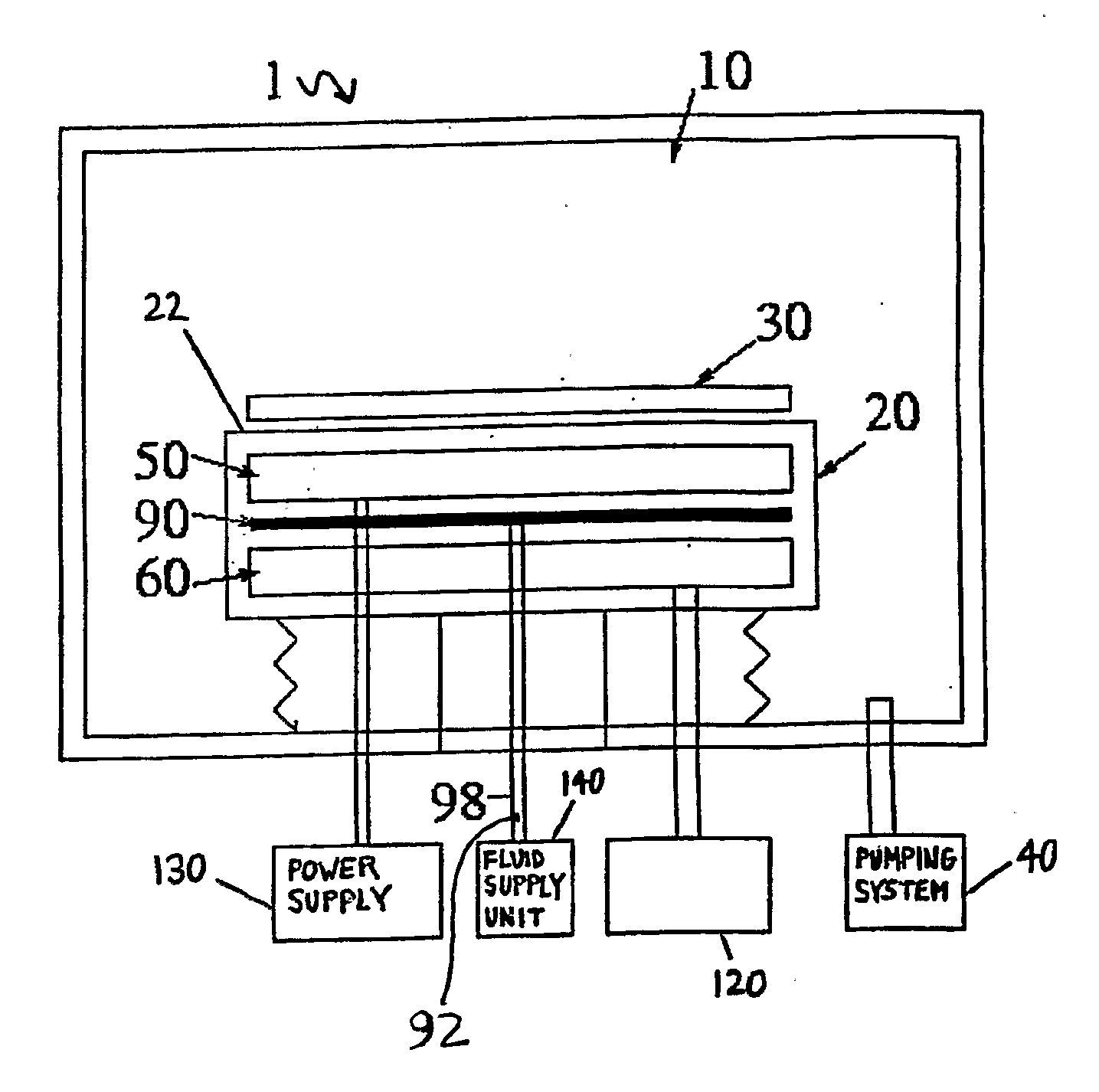
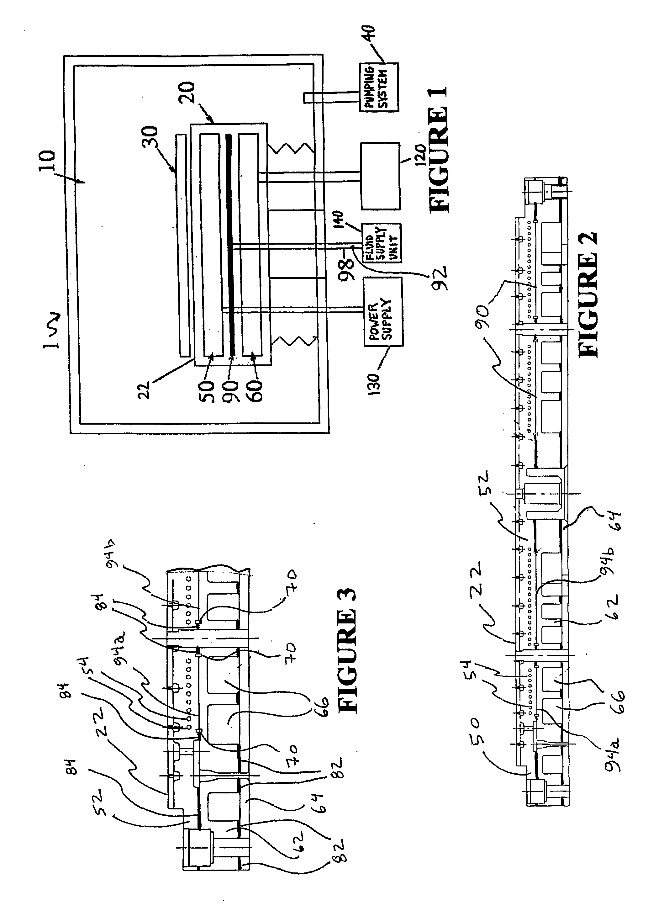
[0019]FIG. 1 illustrates a semiconductor processing system 1, which can be used for chemical and / or plasma processing, for example. The processing system 1 includes a vacuum processing chamber 10, a substrate holder 20 having a supporting surface 22, and a substrate 30 that is supported by substrate holder 20. The processing system 1 also includes a pumping system 40 for providing a reduced pressure atmosphere in the processing chamber 10, an embedded electric heating component 50 energized by a power supply 130, and an embedded cooling component 60 with channels for a liquid flow controlled by a cooling channel assembly 120. A fluid gap 90 is provided between the heating component 50 and the cooling component 60. A fluid supply unit 140 is provided to supply and remove ...


PUM

PropertyMeasurementUnit
Temperatureaaaaaaaaaa
Flow rateaaaaaaaaaa
Mechanical propertiesaaaaaaaaaa

Abstract

A substrate holder (20) for supporting a substrate (30). A heating component (50) is positioned adjacent to a supporting surface and between the supporting surface and a cooling component (60). A fluid gap is positioned between the cooling component and the heating component, the fluid gap configured to receive a fluid to increase thermal conduction between the cooling component and the heating component. A brazing material is disposed between the cooling component and the heating component, the brazing material disposed adjacent to the fluid gap.

Description

BACKGROUND OF THE INVENTION [0001] 1. Field of the Invention [0002] The present invention is generally related to semiconductor processing systems and, more particularly, to a substrate holder having a fluid gap and a method of fabricating the substrate holder. [0003] 2. Discussion of the Background [0004] Many processes (e.g., chemical, plasma-induced, etching and deposition) depend significantly on the instantaneous temperature of a substrate (also referred to as a wafer). Thus, the capability to control the temperature of a substrate is an essential characteristic of a semiconductor processing system. Moreover, fast application (in some important cases, periodically) of various processes requiring different conditions within the same vacuum chamber requires the capability of rapid change and control of the substrate temperature. One method of controlling the temperature of the substrate is by heating or cooling a substrate holder (also referred to as a chuck). Methods to accompli...

Claims


Application Information

Patent Timeline
IPC IPC(8): H01L21/30C23C16/458C23C16/46H01L21/00
CPCC23C16/4586H01L21/67109C23C16/466C23C16/46H01L21/67103H01L21/68785
Inventor HAMELIN, THOMAS
Owner TOKYO ELECTRON LTD
Learn More