
System for detecting leaks and occlusions in a cryoablation catheter

Active Publication Date: 2006-01-05
CRYOCOR
View PDF62 Cites 11 Cited by
  • Summary
  • Abstract
  • Description
  • Claims
  • Application Information

AI Technical Summary

Benefits of technology

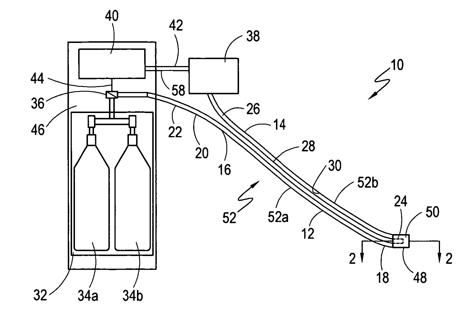
[0008] A vacuum source is positioned at the proximal end of the catheter tube and is connected in fluid communication with the return path for evacuating the fluid flow path. Also located at the proximal end of the catheter tube is a source of fluid refrigerant for introducing pressurized fluid refrigerant into the supply line. Additionally, a supply valve connects the source of fluid refrigerant in fluid communication to the proximal end of the supply line. Functionally, the supply valve is a dual-mode valve for introducing fluid refrigerant into the supply line when the valve is in an “open” position, and for preventing the flow of fluid refrigerant into the supply line when the valve is in a “closed” position.

Problems solved by technology

Further, it will be appreciated that if the efficient flow of fluid refrigerant through a cryo-catheter is impeded or otherwise altered, the cryoablation catheter cannot be used effectively for its intended purpose.
Several factors may contribute to the inefficient flow of a liquid refrigerant through a cryoablating system.
For example, the failure to maintain adequate flow may result from either a leak or an occlusion in the system.
In either case, i.e. a system failure resulting from either a leak or an occlusion, the system cannot achieve the required tip temperatures and the cryoablation procedure should be stopped.
During an in-vivo check of the fluid integrity of a cryoablation system, a physical inspection of the components of the cryo-catheter is not possible.

Method used


Image

  • System for detecting leaks and occlusions in a cryoablation catheter
  • System for detecting leaks and occlusions in a cryoablation catheter
  • System for detecting leaks and occlusions in a cryoablation catheter

Examples


Embodiment Construction

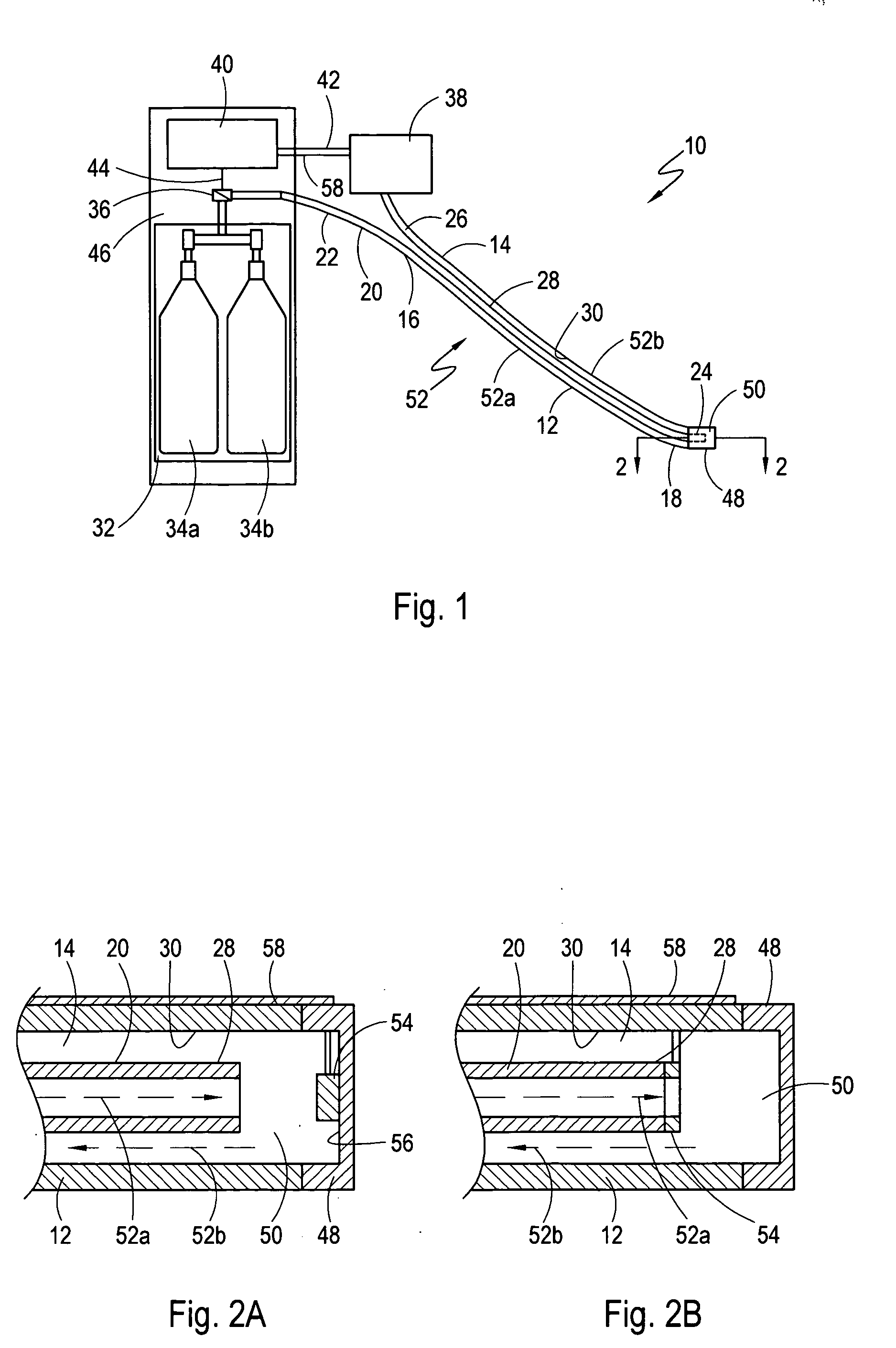
[0018] A system for detecting leaks or occlusions in a cryoablation catheter, in accordance with the present invention, is shown in FIG. 1 and is generally designated 10. As shown, the system 10 includes a catheter tube 12 having a lumen 14 that extends from a proximal end 16 of the catheter tube 12 to a distal end 18 of the catheter tube 12. Additionally, the system 10 includes a supply line 20 having a proximal end 22 and a distal end 24. Structurally, the supply line 20 is coaxially positioned within the lumen 14 of the catheter tube 12 to form a return path 26 between an outer wall 28 of the supply line 20 and an inner wall 30 of the catheter tube 12. As shown in FIG. 1, a source of fluid refrigerant 32 is positioned at the proximal end 16 of the catheter tube 12 for introducing fluid refrigerant into the supply line 20. Preferably, the fluid refrigerant is nitrous oxide (N2O). As contemplated by the present invention, the source of fluid refrigerant 32 comprises one or more sto...


PUM


Abstract

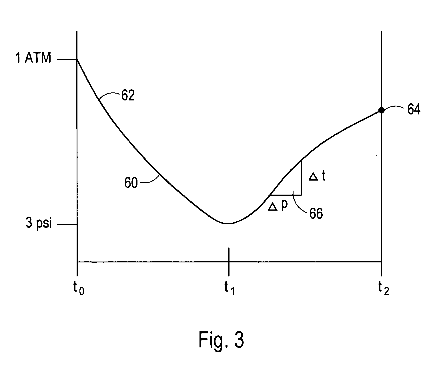
A system for detecting leaks and occlusions in a cryoablation catheter requires monitoring pressure in the catheter at the end of two predetermined time intervals. The catheter includes a catheter tube, a cryo-chamber at the distal end of the catheter, and a supply line for introducing fluid refrigerant into the cryo-chamber. Also included is a pressure sensor mounted in the cryo-chamber for measuring a tip pressure. During the first time interval, fluid refrigerant is prevented from flowing through the catheter while the catheter is evacuated by a vacuum pump. The tip pressure is then measured to detect leaks. During the second time interval, fluid refrigerant is introduced into the cryo-chamber while evacuation continues, and the tip pressure is measured to detect occlusions.

Description

FIELD OF THE INVENTION [0001] The present invention pertains generally to catheters for surgical procedures. More particularly, the present invention pertains to systems and methods for testing the fluid integrity of surgical catheters. The present invention is particularly, but not exclusively useful as a system and method for detecting leaks and occlusions in a cryoablation catheter using pressure data measured at the tip of the cryoablation catheter. BACKGROUND OF THE INVENTION [0002] Cryoablation surgery is used successfully to treat certain forms of cancer, complex arrhythmias and other medical afflictions. During a cryoablation procedure, a cryo-catheter is inserted into the vasculature of a patient for cryo-ablating diseased tissue. Successful cryoablation surgery requires that the portion of the cryo-catheter in contact with the diseased tissue, referred to as the “tip”, is cooled to temperatures on the order of −20° C. to −80° C. To achieve these extremely low temperatures,...

Claims


Application Information

Patent Timeline
IPC IPC(8): A61B18/02
CPCA61B18/02A61B2018/0262A61B2018/0212A61B2017/00725
Inventor RYBA, ERICKUDARAVALLI, RAVIKUMAR
Owner CRYOCOR
Learn More