System and method for controlling flow in a well production system

Active Publication Date: 2016-06-23
BAKER HUGHES OILFIELD OPERATIONS LLC
View PDF10 Cites 13 Cited by
  • Summary
  • Abstract
  • Description
  • Claims
  • Application Information

AI Technical Summary

Benefits of technology

This patent describes a system for controlling the flow of liquids and gases in a horizontal well production system. It includes a valve with an orifice and an actuator that opens the valve when there is liquid in the gap between the casing and tube, allowing the liquid to flow into the tube, and closes the valve when there is gas in the gap, preventing the gas from flowing in. The technical effect of this system is to optimize the production of liquids from horizontal wells and prevent the formation of gas bubbles that can damage equipment.

Problems solved by technology

The gas that escapes past the liquid blockage is often referred to as a “gas slug”, and is known to interfere with the operation of the pump, resulting in reduced production and damage to the pump.
Production zones further away from the pump intake deliver fluids less effectively because of increased flow resistance between the production zone and the pump.
Such drawbacks reduce the production rate and the total recovery of resources from the well.

Method used


Image

  • System and method for controlling flow in a well production system
  • System and method for controlling flow in a well production system
  • System and method for controlling flow in a well production system

Examples


Embodiment Construction

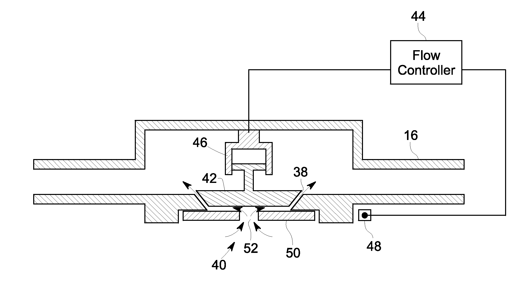
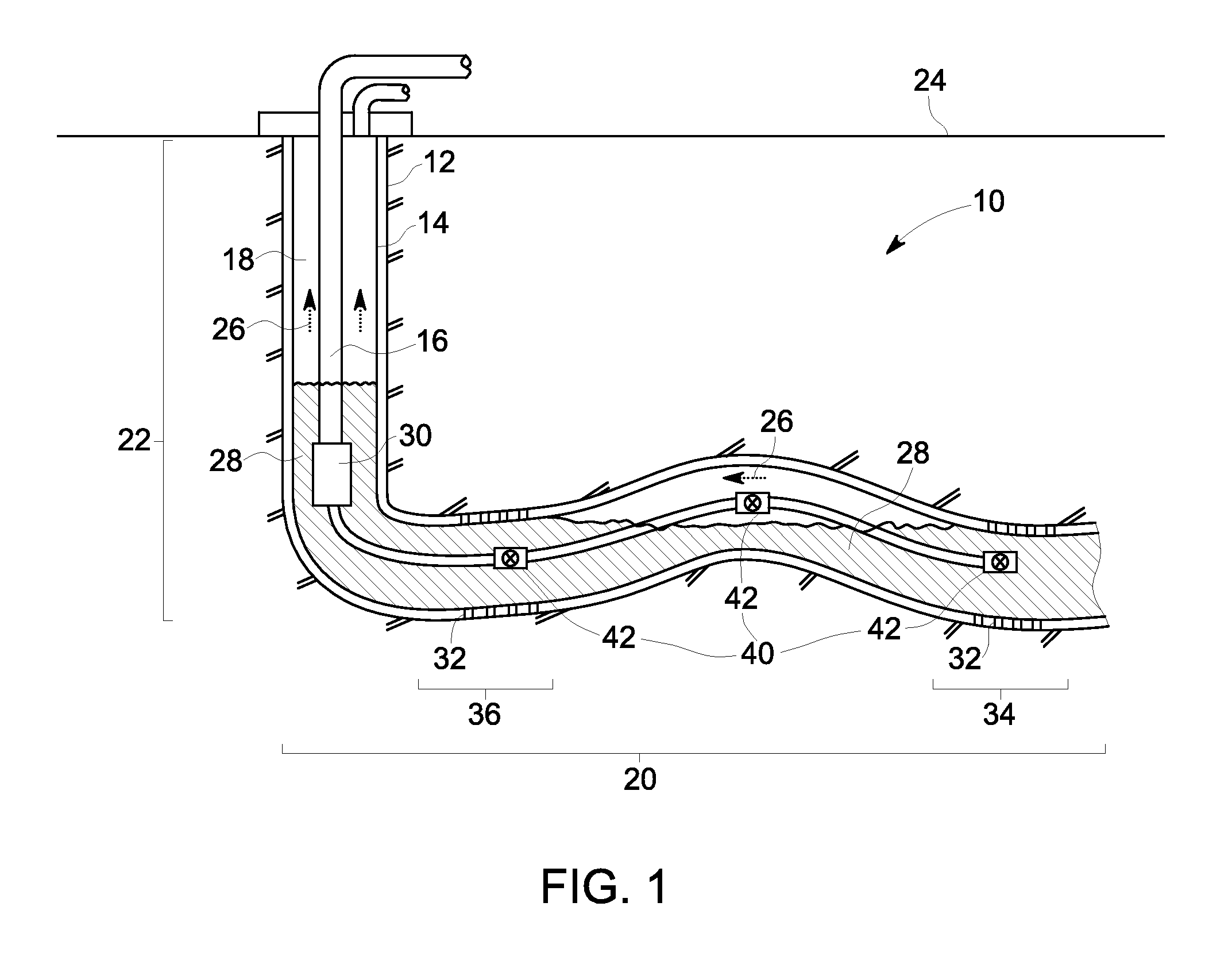
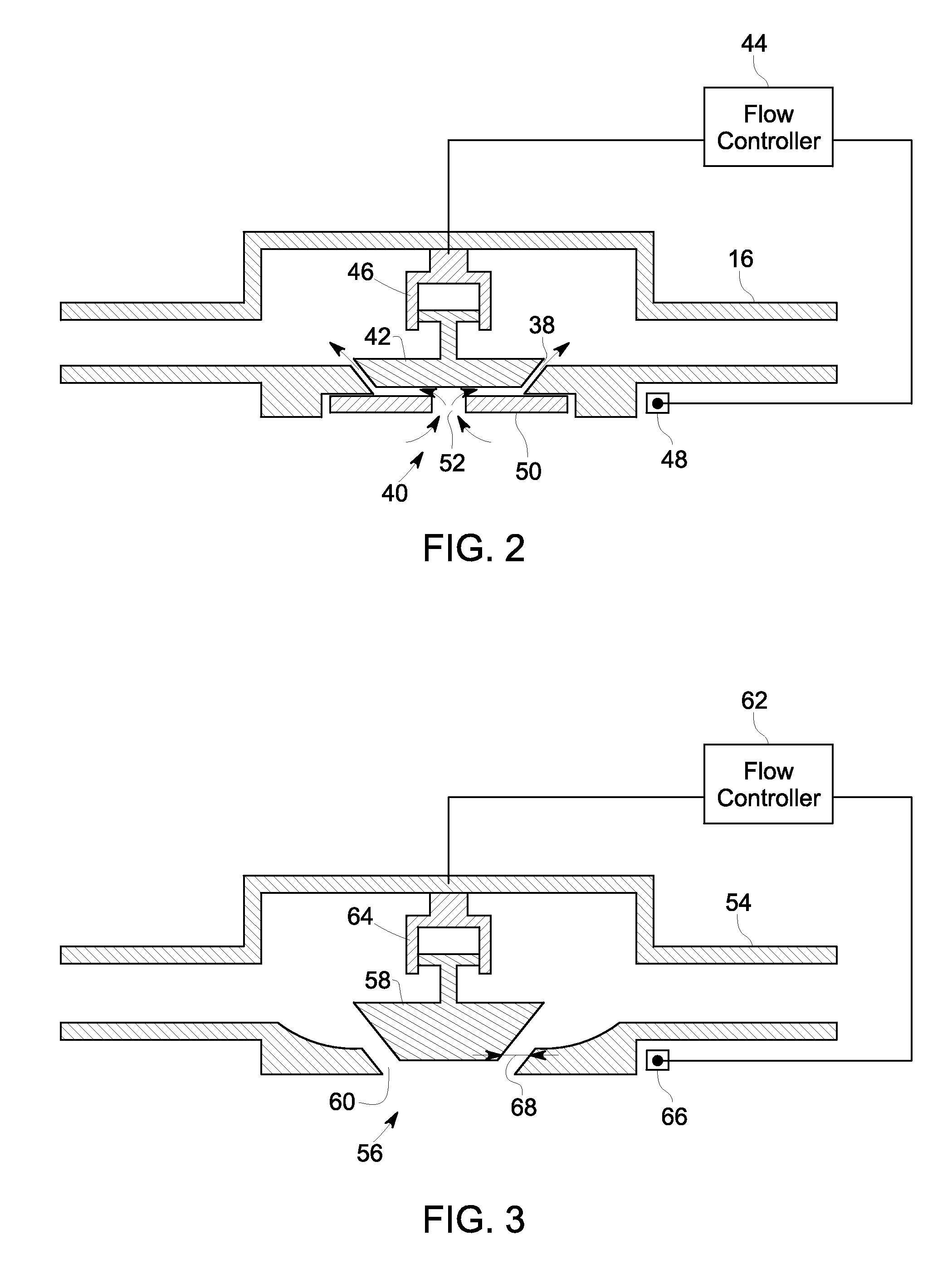
[0013]In accordance with certain embodiments of the present invention, a flow control system for a horizontal well production system is disclosed. The flow control system includes a valve having an orifice, coupled to a tube and disposed proximate to an intake opening of the tube. The orifice may be a fixed orifice or a variable orifice. The tube is disposed within a casing of the horizontal well production system and a gap is formed between the tube and the casing. The flow control system includes an actuator coupled to the valve and configured to open the valve in response to the presence of a liquid in the gap, proximate to the intake opening, to permit flow of the liquid into the tube via the intake opening, and to close the valve in response to presence of a gas in the gap, proximate to the intake opening, to prevent flow of the gas into the tube via the intake opening. In accordance with certain other embodiments, a horizontal well production system having an exemplary flow co...


PUM


Abstract

A flow control system is provided for a horizontal well production system having a casing, a tube having an intake opening and disposed within the casing, and a gap formed between the casing and the tube. The flow control system includes a valve having an orifice, coupled to the tube and disposed proximate to the intake opening. The flow control system further includes an actuator coupled to the valve and configured to open the valve in response to a presence of a liquid in the gap, proximate to the intake opening, to permit flow of the liquid into the tube via the intake opening, and to close the valve in response to a presence of a gas in the gap, proximate to the intake opening, to prevent flow of the gas into the tube via the intake opening.

Description

BACKGROUND[0001]The invention relates generally to oil wells and, more specifically, to a system and method for controlling flow in a horizontal well production system.[0002]Generally, pumping systems are used in a wide variety of environments, including wellbore applications for pumping production fluids, such as water or petroleum. The pumping systems typically include, among other components, a pump positioned at a sufficient depth such that fluids can be lifted to a surface without reliance on reservoir pressure alone. The function of the pump is to reduce a bottom hole pressure and increase a rate of production. The pump may be an electric submersible pump, a rod pump, a progressing cavity pump, or the like. Many of such wells deviate from a straight path in order to enter production zones and follow geological formations that are often within a narrow band. Further, these directionally drilled wells often extend vertically down to reach the depth of the production formation an...

Claims


Application Information

Patent Timeline
IPC IPC(8): E21B34/08E21B43/12
CPCE21B43/121E21B34/08E21B43/32F16K31/122F16K31/26F16K37/005F16K33/00
Inventor VAN DAM, JEREMY DANIELZIERER, JR., JOSEPH JOHNHUGHES, MICHAEL FRANKLINZHANG, ZHIPENG
Owner BAKER HUGHES OILFIELD OPERATIONS LLC
Why Eureka
Try Eureka