Overcurrent Detection Circuit and Power Supply Apparatus Provided Therewith
a detection circuit and power supply technology, applied in the direction of pulse technique, process and machine control, instruments, etc., can solve the problems of failure to start, start-up failure, start-up failure, etc., to enhance the reliability reduce the mounting area of the power supply apparatus, and ensure the effect of overcurrent protection
- Summary
- Abstract
- Description
- Claims
- Application Information
AI Technical Summary
Benefits of technology
Problems solved by technology
Method used
Image
Examples
first embodiment
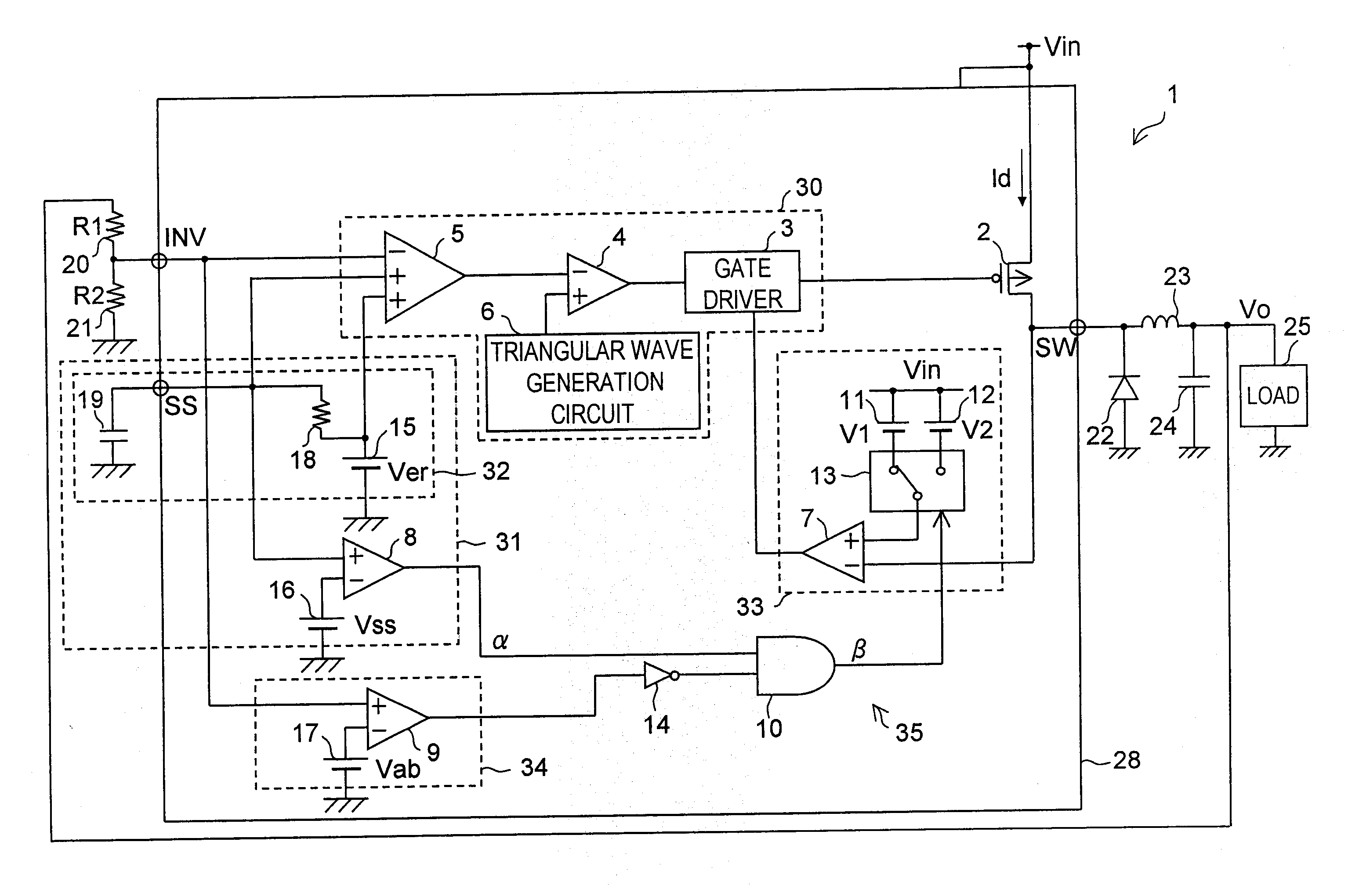
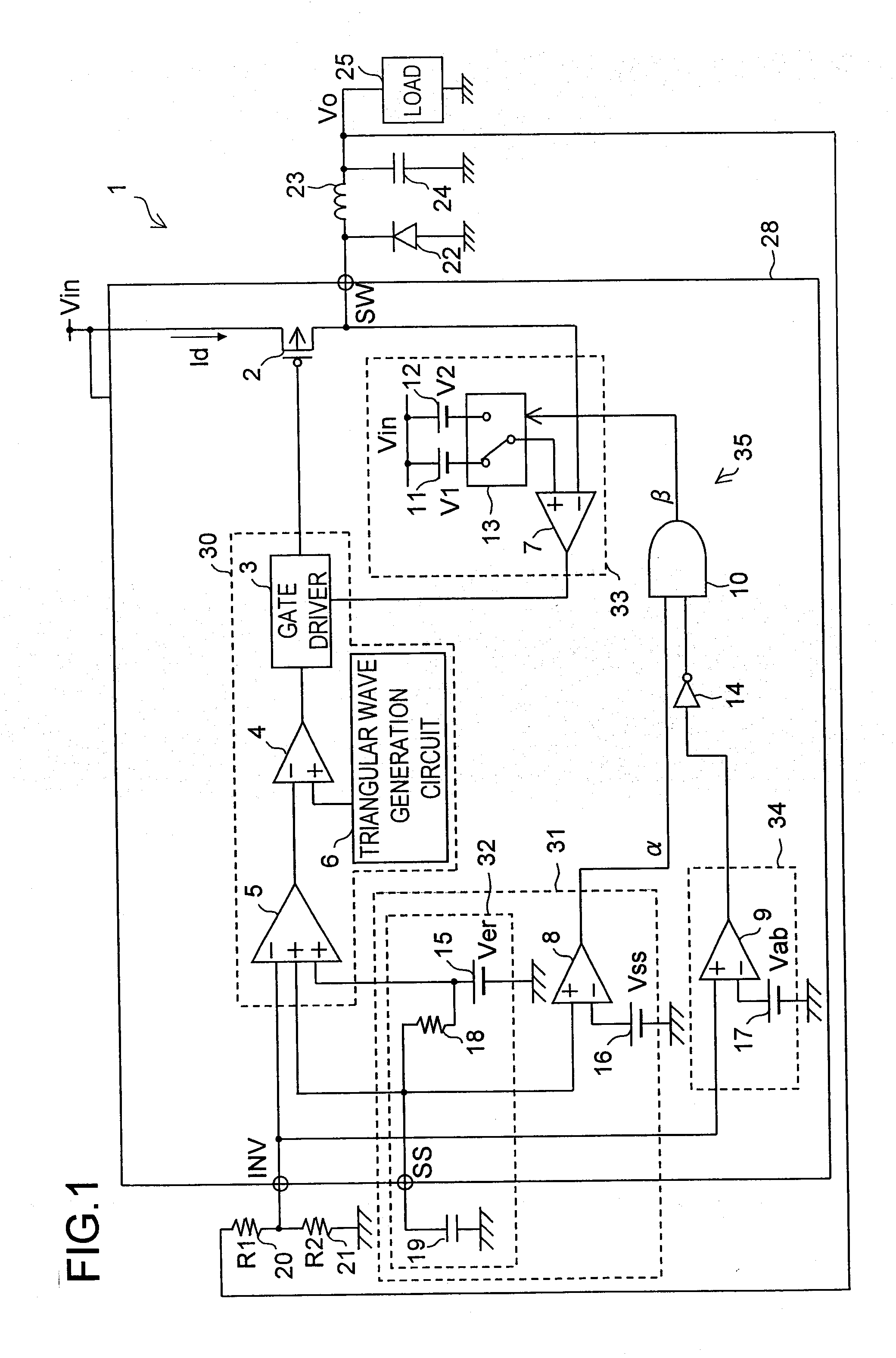
[0063] Hereinafter, a first embodiment of the overcurrent detection circuit of the present invention and the power supply apparatus provided with such an overcurrent detection circuit will be described. FIG. 1 is a diagram showing the circuit configuration of a power supply apparatus 1 of the first embodiment.
[0064] (FIG. 1: Description of the Configuration)
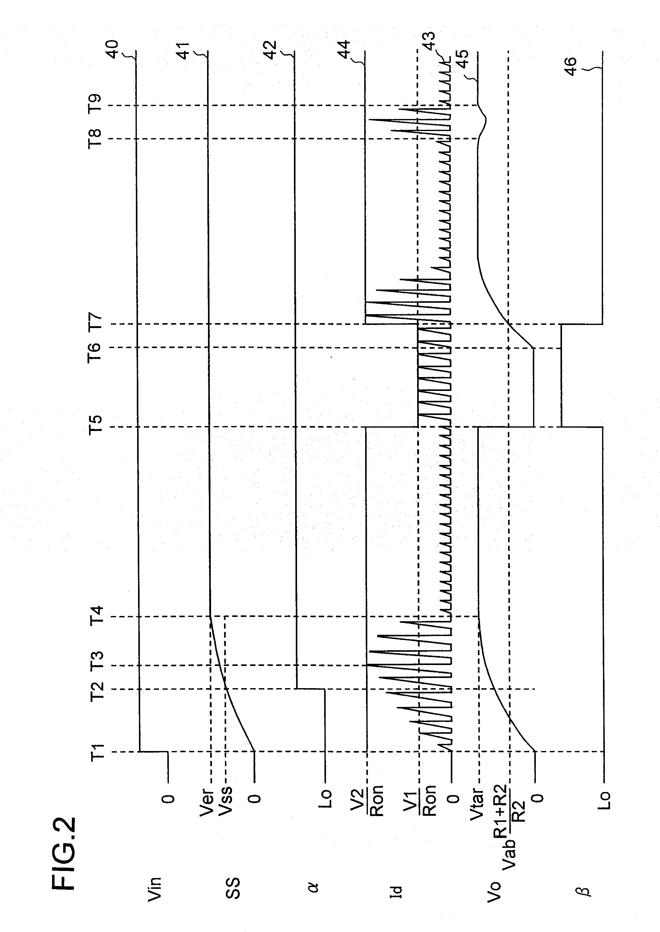
[0065] The source electrode of a P-channel MOS transistor 2 serving as a switching element is fed with an input voltage Vin fed from the outside, and the drain electrode thereof is connected to the inverting input terminal (−) of a comparator 7, to the cathode of a diode 22, and to one end of an inductor 23. The other end of the inductor 23 is grounded via a circuit in which a capacitor 24 for smoothing an output voltage Vo to be applied to a load 25 and the load 25 are connected in parallel. The anode of the diode 22 is grounded. As described above, the drain electrode of the MOS transistor 2 is made to output a current (feed ...
second embodiment
[0117] Next, a second embodiment of the overcurrent detection circuit of the present invention and the power supply apparatus provided with such an overcurrent detection circuit will be described. FIG. 3 is a diagram showing the circuit configuration of a power supply apparatus 51 of the second embodiment. In FIG. 3, such components as are found also in FIG. 1 will be identified with common reference characters and their detailed descriptions will be omitted.
[0118] The power supply apparatus 51 differs from a power supply apparatus 1 in the following respects. The power supply apparatus 51 is provided with, instead of an integrated circuit element 28, an integrated circuit element 58, which does not have a switching element corresponding to a MOS transistor 2. As a switching element corresponding to the MOS transistor 2, a P-channel MOS transistor 52 is provided outside the integrated circuit element 58. The output of a gate driver 3 is fed to the gate electrode of the MOS transist...
modified examples
[0127] In the power supply apparatus 1 and the power supply apparatus 51, a voltage at a node at which the resistor 20 and the resistor 21 are connected together is applied to the non-inverting input terminal (+) of the comparator 9. It is to be understood, however, that the circuit configurations shown in FIGS. 1 and 3 may be modified so that the output voltage Vo is applied, as it is, to the non-inverting input terminal (+) of the comparator 9.
[0128] Moreover, the soft-start circuit 32 of the power supply apparatus 1 and the soft-start circuit 36 of the power supply apparatus 51 can be replaced by each other.
[0129] Furthermore, the present invention can be applied not only to the power supply apparatus 1 (see FIG. 1) or the power supply apparatus 51 (see FIG. 3) but to power supply apparatuses provided with various switching regulators or DC-DC converters, for example. Still further, the present invention can be applied to power supply apparatuses provided with a series regulato...
PUM
 Abstract
Description
Claims
Application Information
 - R&D
- Intellectual Property
- Life Sciences
- Materials
- Tech Scout
- Unparalleled Data Quality
- Higher Quality Content
- 60% Fewer Hallucinations
Browse by: Latest US Patents, China's latest patents, Technical Efficacy Thesaurus, Application Domain, Technology Topic, Popular Technical Reports.
© 2025 PatSnap. All rights reserved.Legal|Privacy policy|Modern Slavery Act Transparency Statement|Sitemap|About US| Contact US: help@patsnap.com


