Impact energy absorbing knee bolster system

a technology of energy absorption and knee bolster, which is applied in the direction of vehicular safety arrangements, pedestrian/occupant safety arrangements, vehicular components, etc., can solve the problems of not being able to efficiently absorb impact energy, and achieve the effects of efficient absorption of impact energy, and promoting deformation during collision

Inactive Publication Date: 2007-09-27
NISSAN MOTOR CO LTD
View PDF11 Cites 27 Cited by
  • Summary
  • Abstract
  • Description
  • Claims
  • Application Information

AI Technical Summary

Benefits of technology

[0007]One object of the present invention is to provide an impact energy absorbing knee bolster system and a method for absorbing impact energy of a passenger's knee that can efficiently absorb the impact energy regardless of whether the direction in which a passenger's knees impact the knee bolster is laterally offset in the widthwise direction of the vehicle, the vertical direction of the vehicle, or both. Another object is to provide a vehicle equipped with such an impact energy absorbing knee bolster system.

Problems solved by technology

However, since the conventional knee bolster is mounted such that its angle with respect to the vertical direction is fixed, it may not be able to absorb the impact energy efficiently when the physique of the passenger is such that passenger's knees are vertically offset with respect to the knee bolster.

Method used


Image

  • Impact energy absorbing knee bolster system
  • Impact energy absorbing knee bolster system
  • Impact energy absorbing knee bolster system

Examples


first embodiment

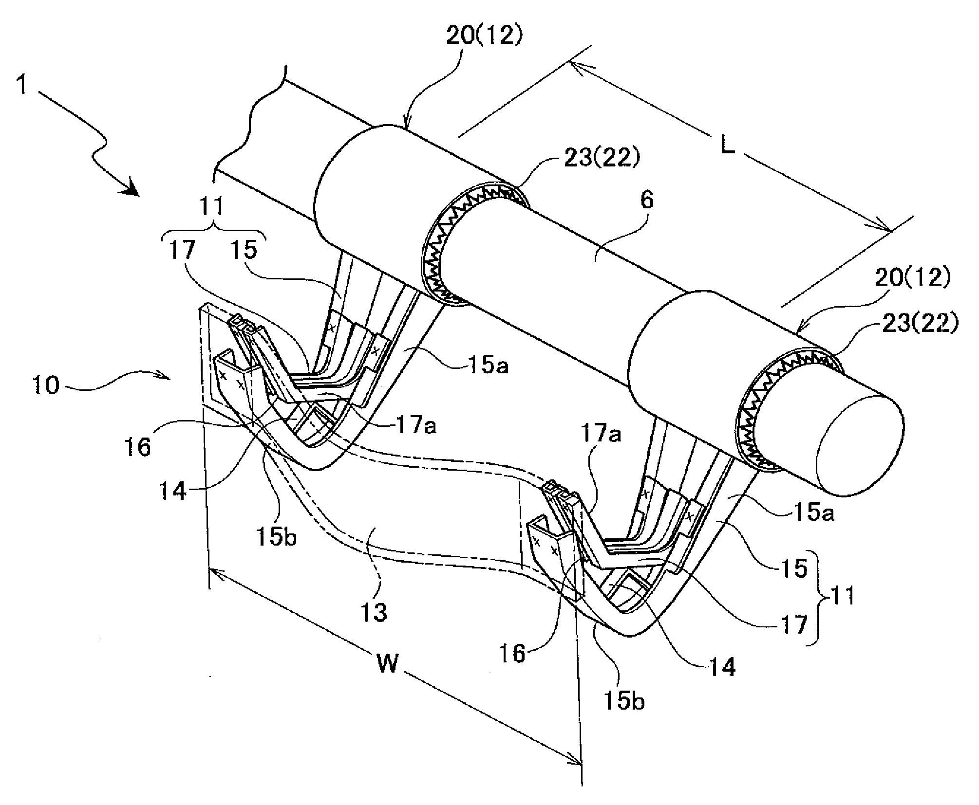
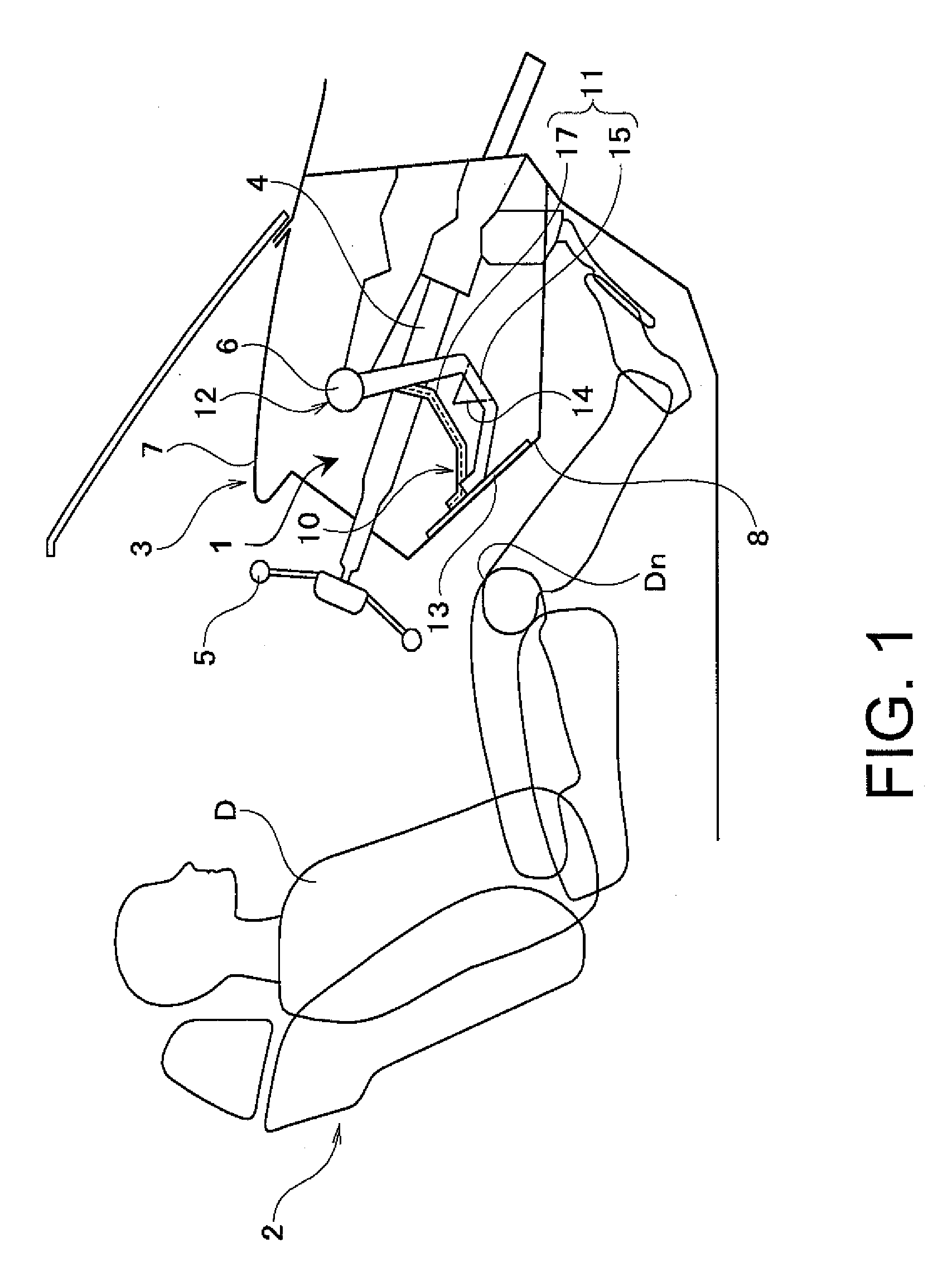
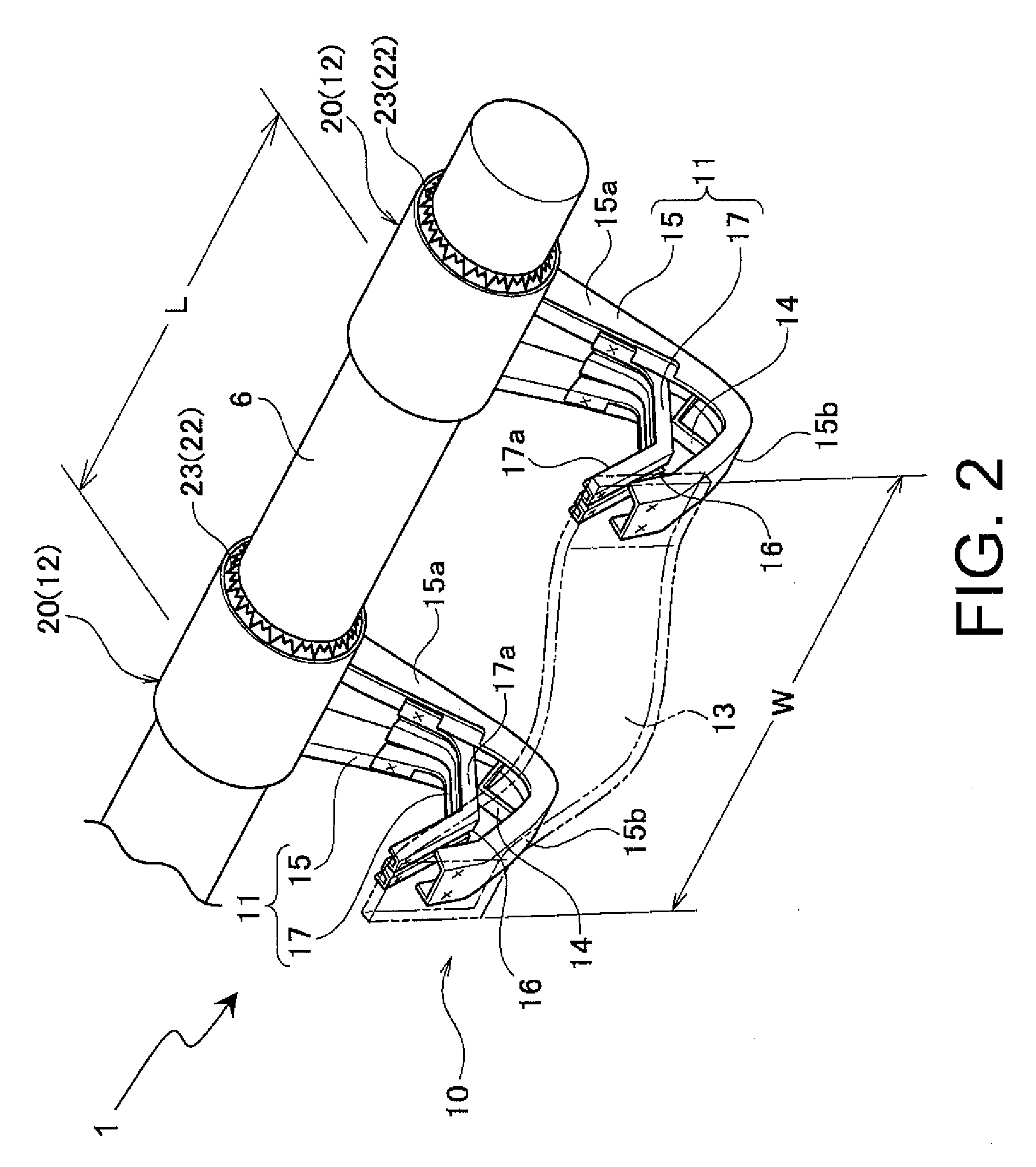
[0047]Referring initially to FIGS. 1 to 8, an impact energy absorbing knee bolster system 1 is illustrated in accordance with the present invention. FIG. 1 is a simplified cross sectional view of a front section of a passenger compartment in which the impact energy absorbing knee bolster system 1 is installed. FIG. 2 is a perspective view illustrating how the impact energy absorbing knee bolster system 1 is mounted. FIG. 3 is an exploded perspective view of the impact energy absorbing knee bolster system 1.

[0048]As shown in FIG. 1, in this illustrated embodiment, the impact energy absorbing knee bolster system 1 absorbs the impact energy from the legs of a driver D sitting in a driver's seat 2. An instrument panel 3 exists in front of the driver's seat 2 with a steering column 4 passes through the instrument panel 3. A steering wheel 5 is mounted to a rearward end of the steering column 4. The steering column 4 is supported on a steering member 6, which extends along the widthwise (...

fourth embodiment

[0092]Also, similarly to the fourth embodiment, the steering member 6 and the arm guides 21 both have circular cross sectional shapes and the arm guides 21 are fitted directly onto the steering member 6 such that they can rotate about the steering member 6.

[0093]In this embodiment, each of the rotational energy absorbing members 22 includes a pair of axial direction movement structures 25 and a pair of load limiting springs 29. The axial direction movement structures 25 move the arm guides 21 along the direction of a rotational axis when the arm guide 21 rotates relative to the steering member6. The load limiting springs 29 connect the arm guides 21 and the steering member 6 together along the direction of the rotational axis.

[0094]As shown in FIG. 19, each of the axial direction movement structures 25 includes the V-shaped notch 25a and the guide pin 25b, the same as in the fourth embodiment. However, in this embodiment, the axial direction movement structures 25 are provided on th...


PUM


Abstract

An impact energy absorbing knee bolster system is basically provided with a lateral offset input restriction structure and a vertical offset input absorption structure. The lateral offset input restriction structure restricts a lateral offset input component of an impact load imparted by a passenger's knee against the knee bolster to lateral direction and promotes deformation of the knee bolster during a collision. The vertical offset input absorption structure absorbs a vertical offset input component of the impact load imparted by the passenger's knee against the knee bolster and to promote deformation of the knee bolster during the collision.

Description

CROSS-REFERENCE TO RELATED APPLICATIONS[0001]This application claims priority to Japanese Patent Application No. 2006-080220, filed on Mar. 23, 2006 and Japanese Patent Application No. 2006-347926, filed on Dec. 25, 2006. The entire disclosures of Japanese Patent Application Nos. 2006-080220 and 2006-347926 are hereby incorporated herein by reference.BACKGROUND OF THE INVENTION[0002]1. Field of the Invention[0003]The present invention relates to a knee bolster for protecting the knees of a passenger during a vehicle collision and a vehicle equipped with the knee bolster. More specifically, the present invention relates to impact energy absorbing knee bolster system that can absorb the impact energy irrespective of variations in the position of the passenger's knee relative to the knee bolster.[0004]2. Background Information[0005]Vehicles are typically provided with a knee bolster. In a case of a conventional driver's side knee bolster, the knee bolster is typically mounted to the st...

Claims


Application Information

Patent Timeline
Patent Type & Authority Applications(United States)
IPC IPC(8): B60R21/045
CPCB60R21/045B60R2021/0051B60R21/05B60R21/206B60R2021/0414
Inventor MAKITA, MASASHIKOBAYASHI, IZUMIPAL, CHINMOY
Owner NISSAN MOTOR CO LTD
Why Eureka
Try Eureka