
Impact energy absorbing knee bolster system

a technology of impact energy and knee bolster, which is applied in the field of knee bolster, can solve the problems of not being able to efficiently absorb impact energy, and achieve the effect of efficient absorption of impact energy

Inactive Publication Date: 2007-12-06
NISSAN MOTOR CO LTD
View PDF13 Cites 2 Cited by
  • Summary
  • Abstract
  • Description
  • Claims
  • Application Information

AI Technical Summary

Benefits of technology

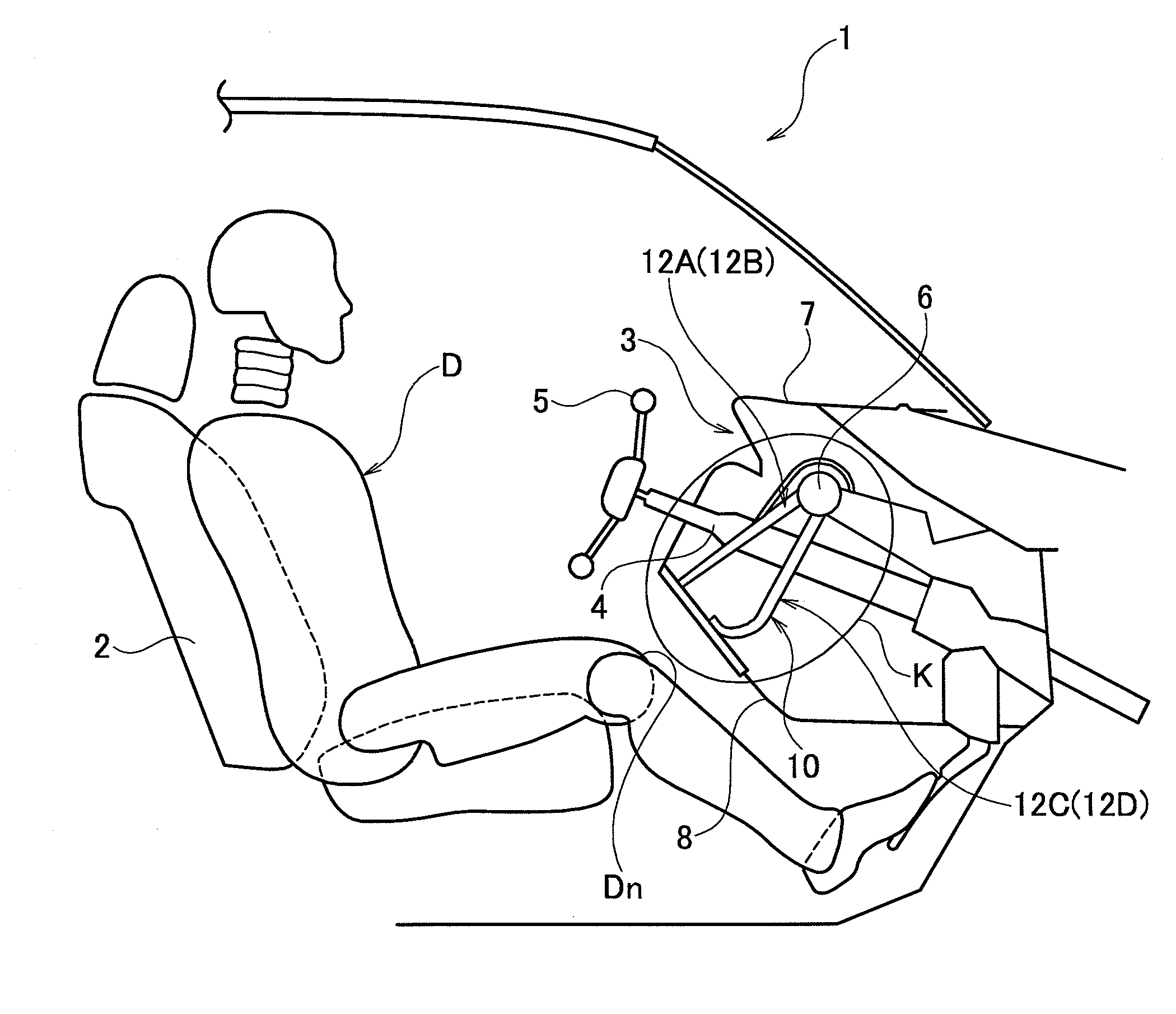
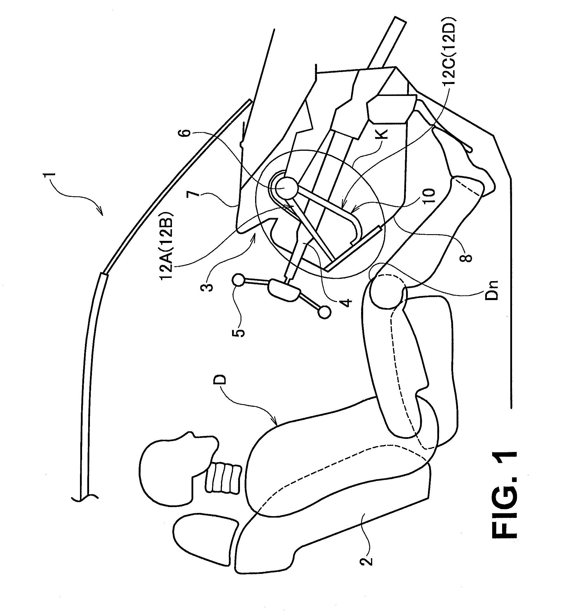
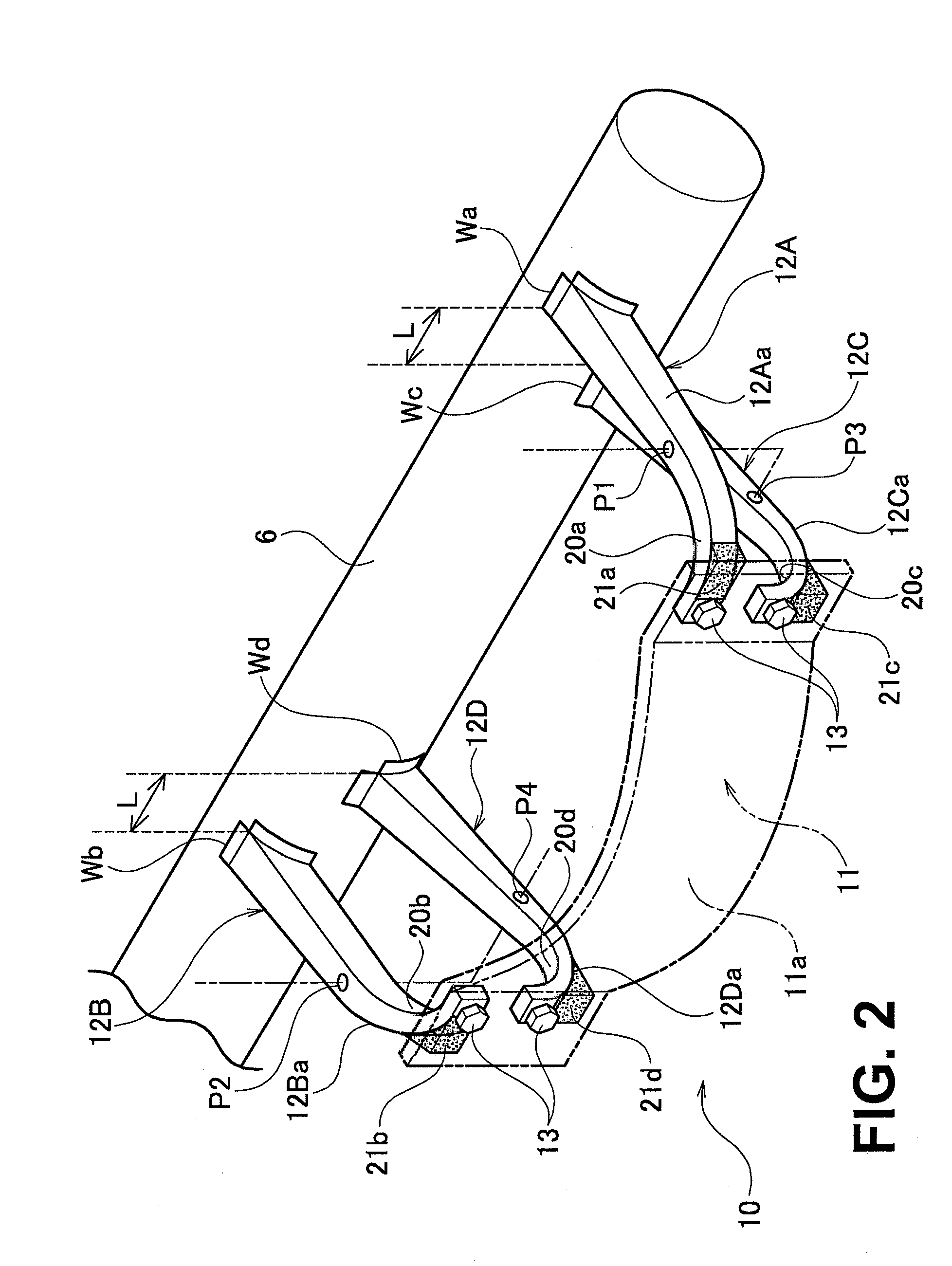
The present invention provides an impact energy absorbing knee bolster system that can efficiently absorb the impact energy of a passenger's knee, regardless of whether the direction in which the passenger's knees impact the knee bolster is laterally offset in the widthwise direction of the vehicle, offset in the vertical direction of the vehicle, or both. The system includes a load input part that contacts the passenger's knee during a collision and a deformation accepting structure that deforms in response to an impact load imparted by the passenger's knee. The deformation accepting structure includes a plurality of collapsing parts that form wedge-shaped spaces between them and the load input part. Each collapsing part has an inflection point with a longitudinal position between a forward end and a rearward end, and the longitudinal positions of the inflection points differ for an upper collapsing part and a lower collapsing part. This results in a more efficient absorption of impact energy, regardless of the direction in which the passenger's knees impact the knee bolster.

Problems solved by technology

However, since this knee bolster is mounted such that its angle with respect to the vertical direction is fixed, it may not be able to absorb the impact energy efficiently when the physique of the passenger is such that the passenger's knees are vertically offset with respect to the knee bolster.

Method used


Image

  • Impact energy absorbing knee bolster system
  • Impact energy absorbing knee bolster system
  • Impact energy absorbing knee bolster system

Examples


second embodiment

[0071]FIGS. 10 to 12 show a second embodiment of the present invention. Parts that are the same as the parts of the first embodiment are indicated with the same reference numerals and explanations thereof are omitted for the sake of brevity. FIG. 10 is a perspective view showing how the knee bolster is mounted, FIG. 11 is an exploded perspective view of the knee bolster, and FIG. 12 is a simplified side elevational view showing how the knee bolster is mounted.

[0072]As shown in FIGS. 10 to 12, a knee bolster 10A in accordance with this embodiment is basically the same as the knee bolster 10 of the first embodiment. The knee bolster 10A includes the plate 11 and the connecting members 12A to 12D with the connecting members 12A to 12D having the curved sections 20a to 20d at the rearward ends thereof. The wedge-shaped spaces 21a to 21d are formed between the curved sections 20a to 20d and the plate 11.

[0073]Also similarly to the first embodiment, the curve directions of the curved sect...

third embodiment

[0079]FIGS. 13 to 16 show a third embodiment of the present invention. Parts that are the same as the parts of the first embodiment are indicated with the same reference numerals and explanations thereof are omitted for the sake of brevity. FIG. 13 is a perspective view showing how the knee bolster is mounted, FIG. 14 is an exploded perspective view of the knee bolster, FIG. 15 is a simplified side elevational view showing how the knee bolster is mounted, and FIG. 16 illustrates a knee of a passenger impacting the knee bolster.

[0080]As shown in FIGS. 13 to 15, a knee bolster 10B in accordance with this embodiment is basically the same as the knee bolster 10 of the first embodiment. The knee bolster 10A includes the plate 11 and the connecting members 12A to 12D with the connecting members 12A to 12D having the curved sections 20a to 20d at the rearward ends thereof. The wedge-shaped spaces 21a to 21d are formed between the curved sections 20a to 20d and the plate 11.

[0081]A main dif...

fourth embodiment

[0088]FIGS. 17 to 19 show a fourth embodiment of the present invention. Parts that are the same as the parts of the first embodiment are indicated with the same reference numerals and explanations thereof are omitted for the sake of brevity. FIG. 17 is a perspective view showing how the knee bolster is mounted, FIG. 18 is an exploded perspective view of the knee bolster, and FIG. 19 is an enlarged cross sectional view taken along the section line A-A of FIG. 17.

[0089]As shown in FIGS. 17 and 18, a knee bolster 10C in accordance with this embodiment is basically the same as the knee bolster 10 of the first embodiment. The knee bolster 10C includes the plate 11 and the connecting members 12A to 12D with the connecting members 12A to 12D having the curved sections 20a to 20d at the rearward ends thereof. The wedge-shaped spaces 21a to 21d are formed between the curved sections 20a to 20d and the plate 11.

[0090]The main difference between this embodiment and the previous embodiments is ...


PUM


Abstract

An impact energy absorbing knee bolster system is basically provided with a load input part and a deformation accepting structure. The load input part is arranged to contact a passenger's knee during a collision. The deformation accepting structure is located between a load input part and a vehicle structural member to deform in response to an impact load imparted by the passenger's knee during a collision. The deformation accepting structure includes a plurality of collapsing parts forming wedge-shaped spaces between each of the collapsing parts and the load input part. Each of the collapsing parts has an inflection point with a longitudinal position between a forward end and a rearward end with the longitudinal positions of the inflection points being different for an upper one of the collapsing parts than for a lower one of the collapsing parts.

Description

CROSS-REFERENCE TO RELATED APPLICATIONS[0001]This application claims priority to Japanese Patent Application No. 2006-151628, filed on May 31, 2006 and Japanese Patent Application No. 2007-035238, filed on Feb. 15, 2007. The entire disclosures of Japanese Patent Application Nos. 2006-151628 and 2007-035238 are hereby incorporated herein by reference.BACKGROUND OF THE INVENTION[0002]1. Field of the Invention[0003]The present invention generally relates to a knee bolster for a passenger during a vehicle collision and a vehicle equipped with the knee bolster. More specifically, the present invention relates to a knee bolster system for absorbing an impact of a knee of a passenger against a knee bolster during a collision.[0004]2. Background Information[0005]In the case of a conventional driver's side knee bolster, the knee bolster is typically mounted to the steering column in such a position as to face the knees of a driver using a rubber bushing and a stay such that the knee bolster ...

Claims


Application Information

Patent Timeline
Patent Type & Authority Applications(United States)
IPC IPC(8): B60R21/045B60R21/20B60R21/206B60R21/05
CPCB60R21/045B60R2021/0407B60R2021/0051
Inventor MAKITA, MASASHIPAL, CHINMOYKOBAYASHI, IZUMI
Owner NISSAN MOTOR CO LTD
Learn More