Absorbent pad

Inactive Publication Date: 2007-09-20
ATTENDS HEALTHCARE
View PDF10 Cites 82 Cited by
  • Summary
  • Abstract
  • Description
  • Claims
  • Application Information

AI Technical Summary

Benefits of technology

[0008] It is accordingly an object of the present invention to provide an absorbent pad, for example of the incontinence pad type having improved characteristics of reduction of chance of leakage or spillage. Furthermore, it is an object to provide an improved absorbent pad having improved characteristics of absorption and at the same time provides for comfort for the person using it. Still another object of the present invention is the provision of such a pad, which will be easy and inexpensive to manufacture and rugged and durable in use.
[0010] It is realized that the provision of a pattern in accordance with the characterizing portion of claim 1 provides for channels which allows for keeping the fluff in position and yet providing means for ventilation even after a discharge has been absorbed by the absorbent pad. The bodies also enables improved fluff filling characteristics for each absorbent pad body due to the possible avoidance of sharped angled corners. It is implicit from the wording of the claim that the absorbent bodies has at least 5 edges forming the circumferential edge of a whole body. Hence, the absorbent pad according to the invention provides for improved capability of isolating fluid by absorption in a specific area of the absorbent pad. Furthermore, the stiffness of the absorbent pad may be increased when having joints with three channels meeting instead of for instance long straight channels, which makes the pad easily foldable and possibly easily shrunk dring use leading to lesser comfort experience. The provision of filled bodies also enables a high specific surface of the absorbent pad as a whole. A higher specific surface may be utilized for enhancing the capillary effect for absorption.
[0011] Advantageously, the edges of said whole body has an angle of 105-135°, preferably 118-122°, in relation to nearlying edges thereof. A small angle will reduce the possibility to fully fill the body with fluff leading to basins instead of absorbing corners.

Problems solved by technology

Furthermore, the stiffness of the absorbent pad may be increased when having joints with three channels meeting instead of for instance long straight channels, which makes the pad easily foldable and possibly easily shrunk dring use leading to lesser comfort experience.
A small angle will reduce the possibility to fully fill the body with fluff leading to basins instead of absorbing corners.

Method used


Image

  • Absorbent pad
  • Absorbent pad
  • Absorbent pad

Examples


Embodiment Construction

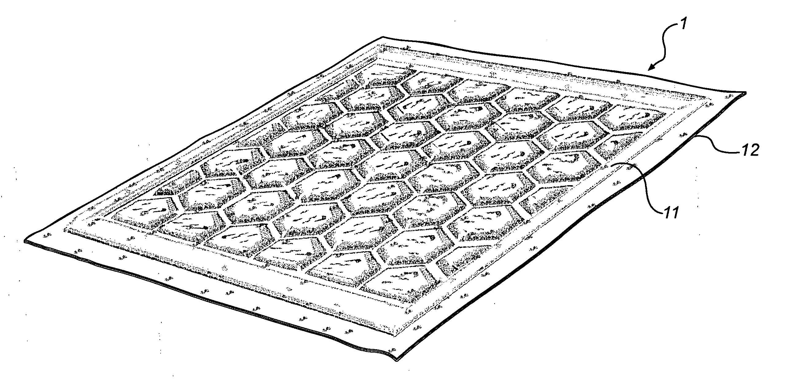
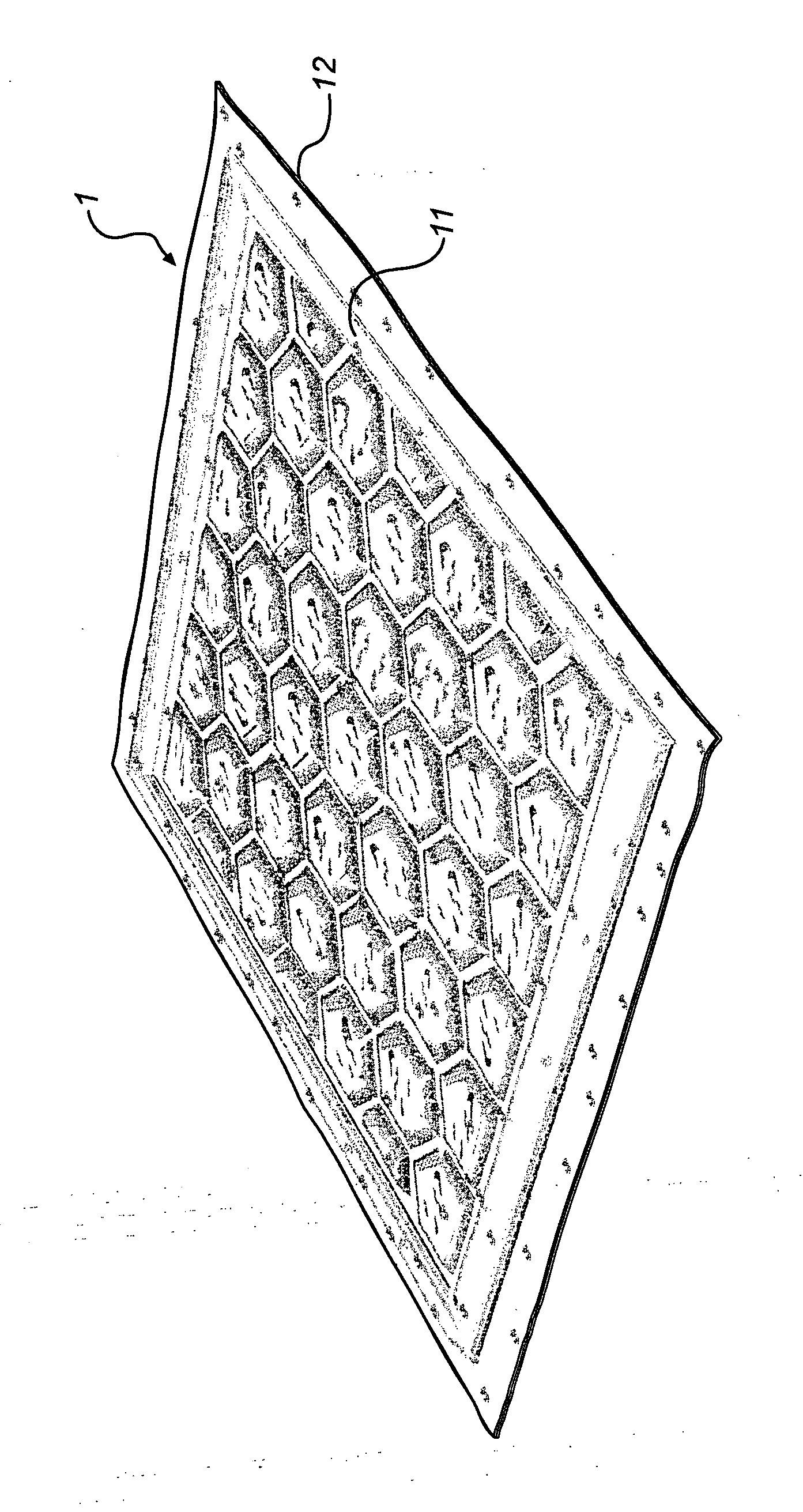
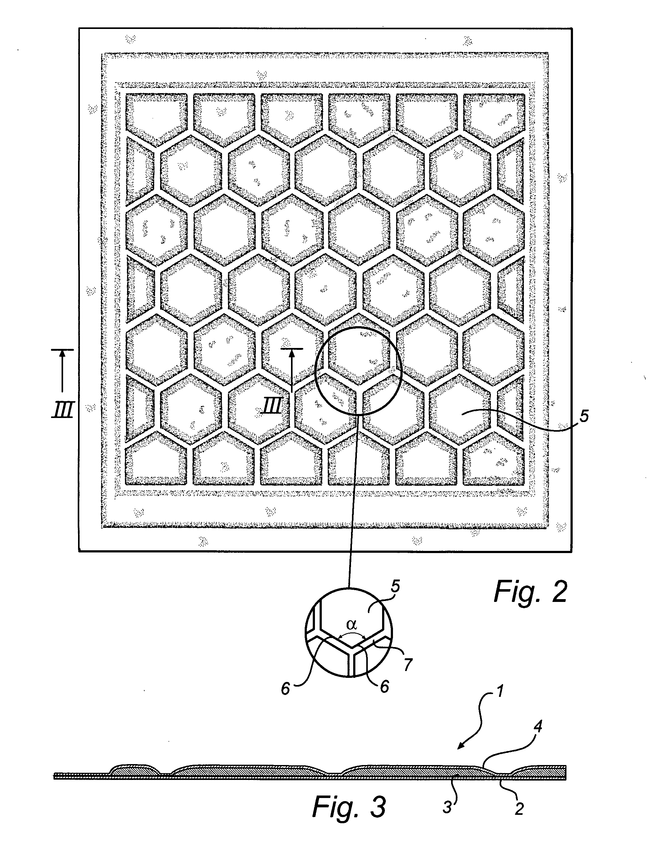
[0021] Referring now to the drawings in greater detail, and first to FIGS. 1-3 thereof, there is shown an absorbent pad 1 according to the present invention, in the form of an incontinence pad 1 of the type used beneath the body of a human in need of the same. The pad 1 includes a liquid-impervious back sheet 2. The material of sheet 2 can be that which is conventionally used as the liquid-impervious back sheet 2 for diapers and incontinence pads and the like, for example polyethylene film of a thickness of 0.010 mm to 0.050 mm, preferably 0.015 to 0.030 mm.

[0022] On top of the sheet 2 are a plurality of spaced bodies 3 of absorbent material, preferably fibrous in nature. This absorbent material is quite conventional and has a high capacity to absorb liquid. A typical such absorbent is a fluff of bleached sulphate pulp made from softwood and having a fiber length of 0.1 mm to 10 mm, preferably 2-5 mm. However, any other conventional absorbent could be used.

[0023] The bodies 3 are ...


PUM


Abstract

According to the invention it is disclosed an absorbent pad (1) comprising a liquid-impervious back sheet (2), a plurality of bodies (3) of liquid-absorbent material disposed on one surface of the back sheet (2), and a liquid-pervious cover sheet (4) covering said bodies (3) of absorbent material and secured to the back sheet (2) along channels (7) which separate said bodies (3) of absorbent material. The channels (7) progresses in a channel-pattern in which three channels (7), meeting in a joint, form respective edges (6) of said whole bodies (3) and said channels (7) being substantially free from absorbent material. A method for the manufacturing of such absorbent pad (1) is also disclosed.

Description

PRIORITY STATEMENT [0001] This application claims benefit of priority under 35 U.S.C. § 119 from European Patent Application No. 06 114 641.1 filed on May 29, 2006, in the European Patent Office, the disclosure of which is incorporated herein by reference in its entirety. FIELD OF THE INVENTION [0002] The present invention relates to absorbent pads, more particularly absorbent pads of the type used as incontinence pads to be positioned under a person. BACKGROUND OF THE INVENTION [0003] It is known to make absorbent pads with flow-spreading depressions or projections. Sanitary napkins, baby diapers and the like have been made with cellulose fluff or crepe wadding material between a cover sheet and an impervious back sheet, and with the absorbent medium embossed with depressions extending transverse to the longitudinal axis of the pad or in various patterns such as diamond, herringbone, sinusoidal, etc. [0004] An alternative on the constructions discussed above involved the applicatio...

Claims


Application Information

Patent Timeline
IPC IPC(8): A61F13/15
CPCA61F13/5323
Inventor BRUUN, JONASLINDQVIST, ARNEHALLGREN, SAMMY
Owner ATTENDS HEALTHCARE
Why Eureka
Try Eureka