
Receiver, transceiver and receiving method

a receiver and transceiver technology, applied in the direction of transmission, electrical equipment, network with variable switch closing time, etc., can solve the problems of many difficulties for transceiver and receiver designers, low level of receiver signal, high cost of duplex filters, etc., to achieve low noise, reduce filter size and cost, the effect of high selectivity

Inactive Publication Date: 2007-09-20
NOKIA CORP
View PDF5 Cites 5 Cited by
  • Summary
  • Abstract
  • Description
  • Claims
  • Application Information

AI Technical Summary

Benefits of technology

[0013] The embodiments of the invention provide several advantages. The proposed filtering arrangement may be implemented on the RFIC of the receiver or transceiver. There is no need for expensive and bulky external filters. Thus, the size and the cost of the filter are considerably lower than in the prior art solutions. Furthermore, the frequency response of the filter is better than in the prior art solutions. For example, a very wideband low noise amplifier input at the receiver may be achieved with a high selectivity. The insertion loss is significantly lower than with external filters.
[0014] The design of the proposed filtering arrangement is simple and it may be configured for use on different frequency bands with minimal changes. The change of the frequency band in use may be performed by software.

Problems solved by technology

The high output power of the transmitter may cause problems to the receiver receiving a very low level signal.
The use of these filters causes many difficulties to transceiver and receiver designers.
Duplex filters are expensive and complicated and increase manufacturing costs.
These components are expensive, impossible to integrate with a standard CMOS or BiCMOS process and also require large areas of PWBs (printed wiring boards).
Such filters also decrease the possibility of modularity and increase the number of I / O's (inputs / outputs) in RFIC's (radio frequency integrated circuits) thus increasing their complexity.
Also, the insertion loss in the receiver front end is significant when considering the total noise figure of the receiver and the sensitivity that can be achieved with it.
The design of band specific filters is complicated, as it requires switches to couple a signal through correct filters to the antenna and to the receiver.

Method used


Image

  • Receiver, transceiver and receiving method
  • Receiver, transceiver and receiving method
  • Receiver, transceiver and receiving method

Examples


Embodiment Construction

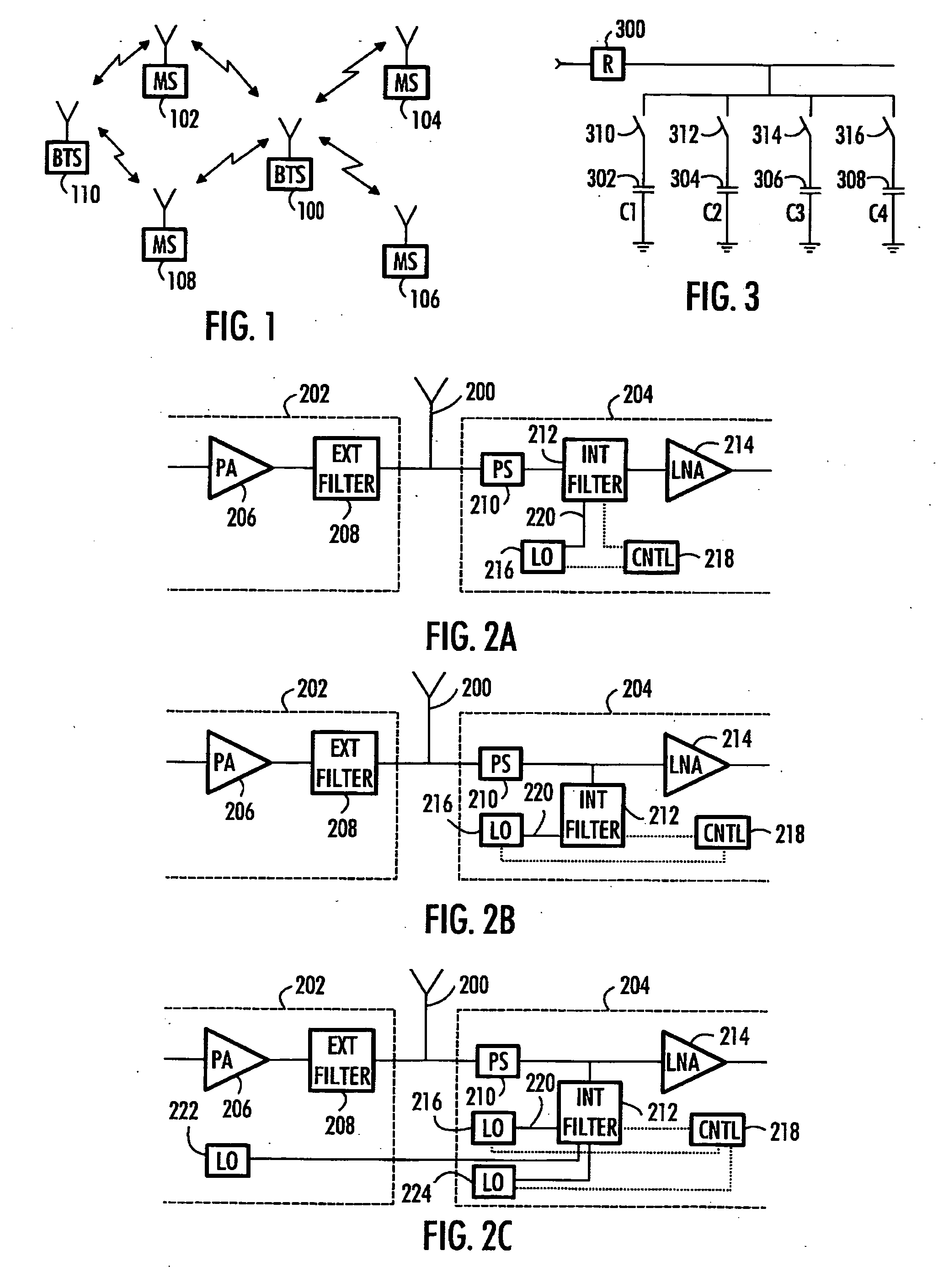
[0023] With reference to FIG. 1, let us examine an example of a telecommunication system in which embodiments of the invention are applicable. FIG. 1 shows a base station 100 which is in connection with terminal equipment 102, 104, 106 and 108. The terminal equipment 102 and 108 may also be in contact with another base station 110. The base station 100 and the terminal equipment 102, 104, 106 and 108 comprise an RF transceiver. Embodiments of the invention may be applied both in base stations and in terminal equipment.

[0024] Different multiple access methods may be used in the telecommunication system in which embodiments of the invention are applicable. The system may utilize CDMA (Code Division Multiple Access) WCDMA (Wide CDMA) or TDMA (Time Division Multiple Access), for example. The access method used is not relevant regarding the embodiments of the invention. Different connections within the system may interfere with each other.

[0025] Also, the transmitter and receiver of ea...


PUM


Abstract

A receiving method, a transceiver and a receiver are provided. The receiver comprises an antenna for receiving a radio frequency signal, a local oscillator, an amplifier for amplifying the received signal, a phase shifter connected between the antenna and the amplifier, the phase shifter converting a high impedance at one end of the phase shifter to a low impedance at the other end, and vice versa. The receiver further comprises a filter, the frequency response of the filter being determined on a frequency related to the frequency of the local oscillator, the filter comprising a switching arrangement which converts the frequency response to radio frequency.

Description

FIELD [0001] The invention relates to filtering in receivers and transceivers, especially in RF receivers and transceivers. BACKGROUND [0002] Receivers of telecommunication systems must tolerate high blocking signals while maintaining their own performance. The blocking signals may originate from nearby external transmitters and interferers. When a transceiver is concerned the cause of a blocking signal may be a transmitter of the same transceiver that is transmitting at the same time a receiver of the transceiver is receiving. The high output power of the transmitter may cause problems to the receiver receiving a very low level signal. [0003] To avoid these blocking effects a duplex filter has been used in transceivers to isolate transceiver and receiver branches from each other. Furthermore, the receiver front end includes various filters in order to filter out-band blockers and interferers. [0004] The use of these filters causes many difficulties to transceiver and receiver desig...

Claims


Application Information

Patent Timeline
IPC IPC(8): H04B1/26
CPCH04B1/28H03H19/008H04B1/40
Inventor VILHONEN, SAMI
Owner NOKIA CORP
Learn More