
Monitoring health of a combustion dynamics sensing system

a sensing system and combustion dynamics technology, applied in the direction of engines, machines/engines, mechanical equipment, etc., can solve the problems of high cost of dynamic condition sensors, system failures caused by excessive dynamics, and the tendency of combustion engines to become less robust against these combustor dynamics

Inactive Publication Date: 2007-09-20
SIEMENS ENERGY INC
View PDF8 Cites 43 Cited by
  • Summary
  • Abstract
  • Description
  • Claims
  • Application Information

AI Technical Summary

Problems solved by technology

As DLN combustion systems are increasingly required to be operated more aggressively with regard to emissions and gas turbine cycling, the combustors tend to become less robust against these combustor dynamics.
Consequently, system failures caused by excessive dynamics become possible.
Such dynamic condition sensors tend to be expensive and typically require continuous maintenance monitoring to ensure that they are functioning properly.
In addition, combustion dynamics sensing system problems, such as water in damping tube of the system or signal amplifier failures, may result in erroneous dynamic condition signals being generated.

Method used


Image

  • Monitoring health of a combustion dynamics sensing system
  • Monitoring health of a combustion dynamics sensing system
  • Monitoring health of a combustion dynamics sensing system

Examples


Embodiment Construction

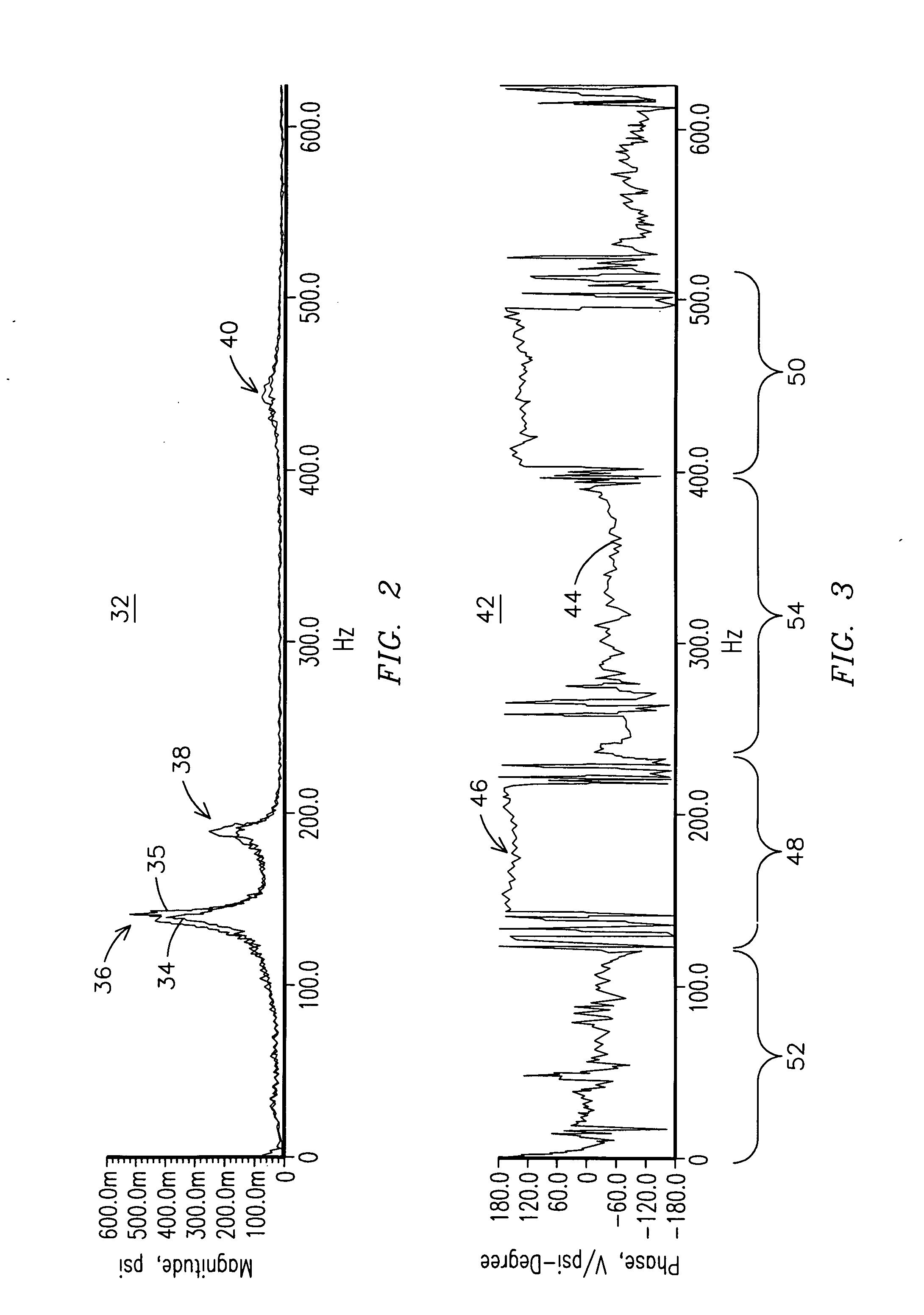
[0007] Individual cans of a can annular combustor of a gas turbine engine may exhibit amplitude spikes at certain acoustic frequencies during operation. FIG. 2 shows an example frequency spectrum 32 of respective Fourier-transformed acoustic waveform signals 34, 35 for two adjacent cans of a conventional DLN-type can annular combustor. As shown in FIG. 2, amplitude spikes 36, 38, 40 typically occur at about 140 Hz, 190 Hz, and 440 Hz, respectively. In addition to exhibiting such amplitude spikes, adjacent cans of a can annular combustor may interact dynamically with one another at these acoustic frequencies. For example, adjacent cans may interact in a push-pull mode, wherein a phase signal corresponding to an amplitude spike for one of the cans of an adjacent pair is 180 degrees out of phase with respect to the other can of the pair. In the case of a can annular combustor having an even number of cans, it has been demonstrated that a phase angle difference between dynamic condition...


PUM


Abstract

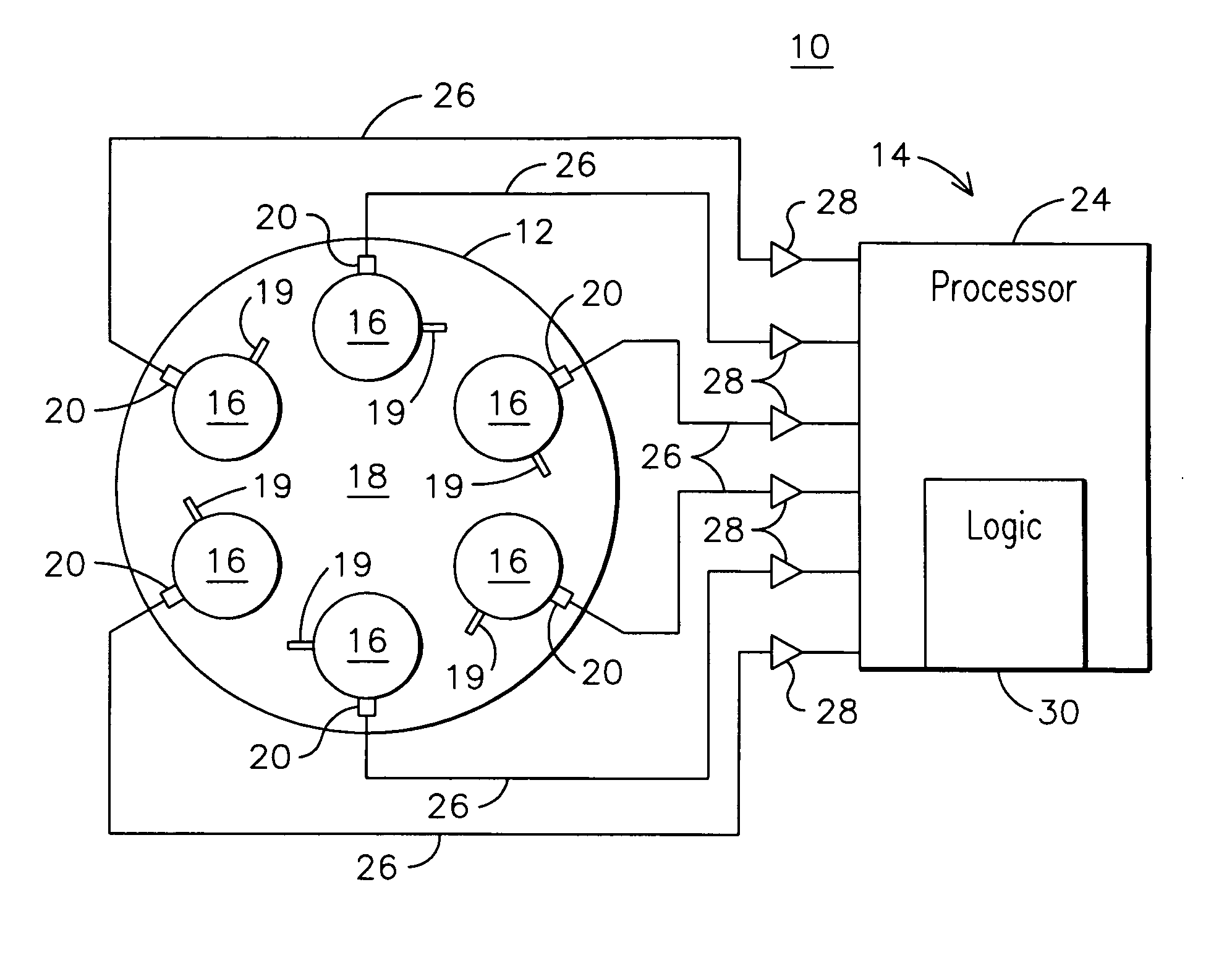
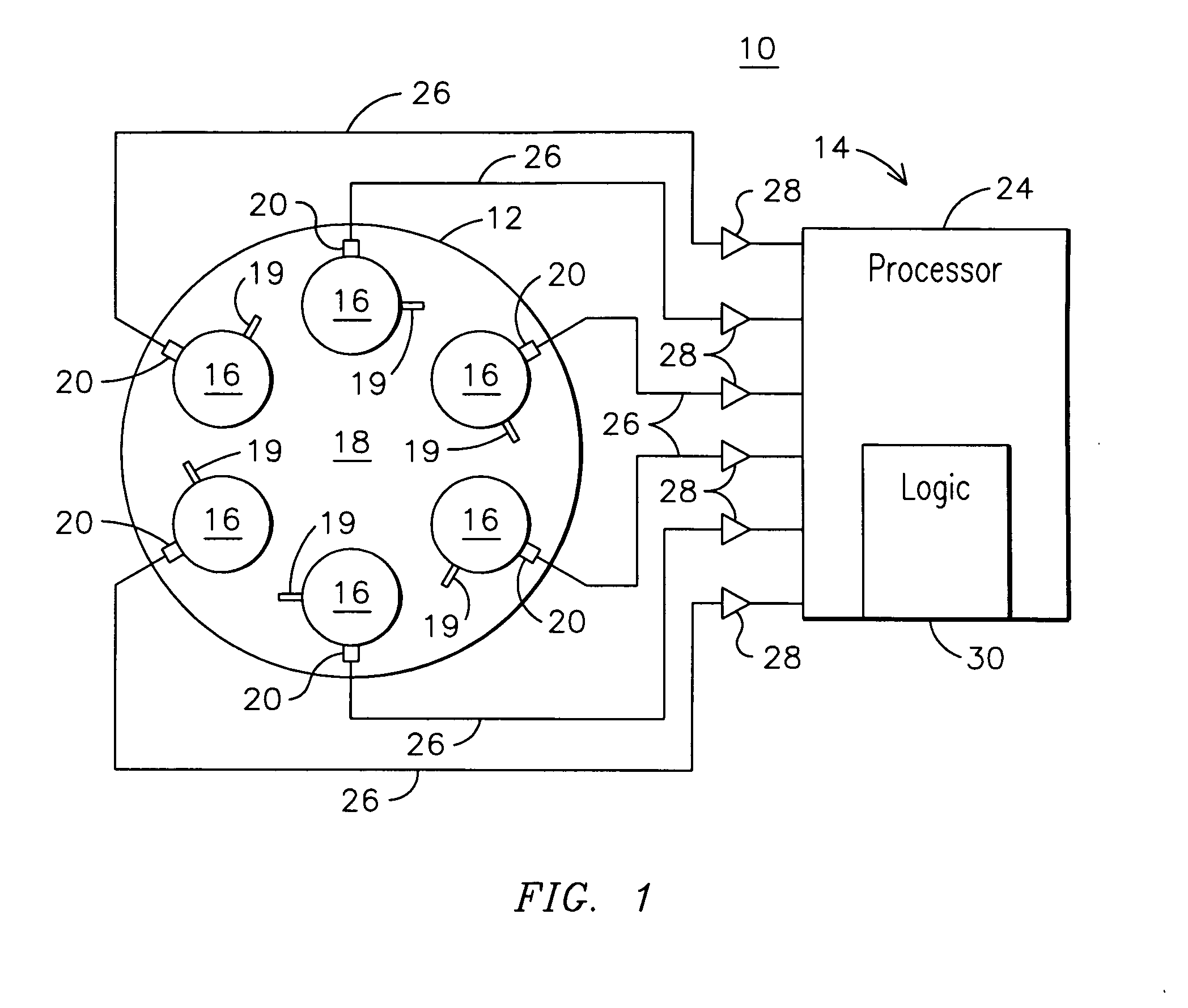
A method and system (14) for monitoring a health of a combustion dynamics sensing system (10) includes monitoring respective dynamic conditions of at least two combustor cans (16) of a can annular combustor (12) of a gas turbine engine with respective dynamic condition sensors (20) associated with each of the cans. The method also includes establishing a baseline relationship between the respective dynamic conditions and then identifying a variance from the baseline relationship indicative of a degraded signal quality provided by a dynamic condition sensor associated with at least one of the cans.

Description

FIELD OF THE INVENTION [0001] The invention relates to gas turbine engines, and more particularly, to a method for monitoring a health of a combustion dynamics sensing system. BACKGROUND OF THE INVENTION [0002] Gas turbines having can-annular combustors are known wherein individual cans, including a combustion zone within the can, feed hot combustion gas into respective individual portions of an arc of a turbine inlet. The individual cans may receive fuel and air for combustion and be disposed in a ring around a central region of a combustor of the engine. Combustion generated dynamic pressure fluctuations, or combustion dynamics, produced in gas turbine engines, and especially in gas turbine engines having Dry, Low NOx (DLN) combustion systems, need to be carefully monitored and controlled to achieve acceptable system durability and reliability. As DLN combustion systems are increasingly required to be operated more aggressively with regard to emissions and gas turbine cycling, the...

Claims


Application Information

Patent Timeline
IPC IPC(8): F02C1/00
CPCF05D2260/80F01D21/003
Inventor BLAND, ROBERT J.JOHNSON, CLIFFORD E.
Owner SIEMENS ENERGY INC
Learn More