Method for compensating thermal displacements

a technology of thermal displacement and compensation method, applied in the field of compensation method, to achieve the effect of improving the accuracy of compensation

Inactive Publication Date: 2007-09-13
CHIRON WERKE
View PDF11 Cites 17 Cited by
  • Summary
  • Abstract
  • Description
  • Claims
  • Application Information

AI Technical Summary

Benefits of technology

[0019] In view of the above, it is one object of the present invention to improve the accuracy of the compensation in the known method without having to accept the time disadvantages which are associated with the direct measurement of the actual displacement.

Problems solved by technology

Specifically, the inventors of the present application have realized that a substantial problem in the known compensation method, which is based on pure temperature measurement, consists in that use is made of a calculating rule which is a function solely of machine type, this calculating rule being determined only once for the appropriate machine type, and not even once is account taken of the individual conditions of the particular machine tools of the corresponding type.

Method used


Image

  • Method for compensating thermal displacements
  • Method for compensating thermal displacements

Examples


Embodiment Construction

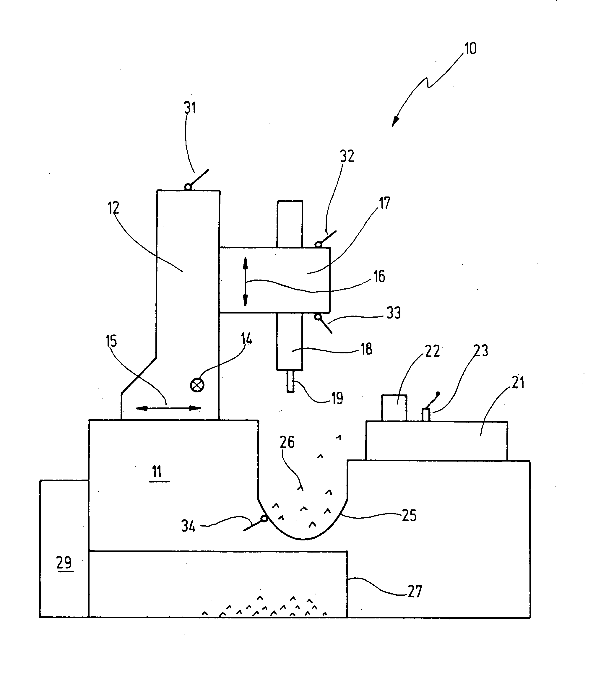
[0048] Denoted by 10 in FIG. 1 is a machine tool which has a machine frame 11 on which a moving column 12 can be traversed in the direction of an X-axis indicated at 14, and in the direction of a Y-axis indicated at 15.

[0049] Supported on the moving column 12 is a spindle head 17 which can be traversed in the direction of a Z-axis indicated at 16 and which carries a tool spindle 18 which holds a tool 19 at its lower end. Various tools 19 can be exchanged in the tool spindle 18 in a way known per se.

[0050] The tool spindle 18, and thus the respective tool 19, can in this way be traversed on the three axes 14, 15, 16 relative to a work table indicated at 21 and on which a workpiece 22 to be machined is indicated.

[0051] In addition to the workpiece 22, a probe 23 which serves as reference point for the coordinate system is provided on the work table 21.

[0052] Further indicated between the work table 21 and the moving column 12 is a chip trough 25 in which chips 26 produced during t...


PUM


Abstract

A method for compensating thermal displacements is carried out on a machine tool having a worktable for mounting workpieces to be machined, and having a tool spindle which can be traversed relative to the worktable on at least one axis and into which it is possible to clamp tools with the aid of which a machining process is carried out on the workpieces. In this case a calculating rule is used to calculate from at least one temperature value currently measured at a measuring point on the machine tool at least one correction value for the at least one axis. The calculating rule is tuned in this case to the respective machining process.

Description

[0001] This is a continuation application of International Patent Application PCT / EP / 2005 / 006783, filed Jun. 23, 2005, designating the United States and published in German as WO 2006 / 029662 A1, which claims priority to German application No. 10 2004 044 838, filed Sep. 13, 2004.BACKGROUND OF THE INVENTION [0002] 1. Field of the Invention [0003] The present invention relates to a method for compensating thermal displacements in the case of a machine tool having a worktable for mounting workpieces to be machined, and having a tool spindle which can be moved relative to the worktable in at least one axis and into which tools can be clamped for performing a machining process on the workpieces, a calculating rule being used to calculate from at least one temperature value currently measured at a measuring point on the machine tool at least one correction value for the at least one axis. [0004] 2. Related Prior Art [0005] Such a method is known from DE 42 03 994 A1. [0006] The requiremen...

Claims


Application Information

Patent Timeline
Patent Type & Authority Applications(United States)
IPC IPC(8): G06F19/00
CPCB23Q11/0007G05B2219/49206G05B19/404
Inventor PRUST, DIRKWINKLER, HANS-HENNING
Owner CHIRON WERKE
Why Eureka
Try Eureka