
Method Of Manufacturing Catalytic Converters, Catalytic Converters, And Method Of Controlling Catalytic Converters

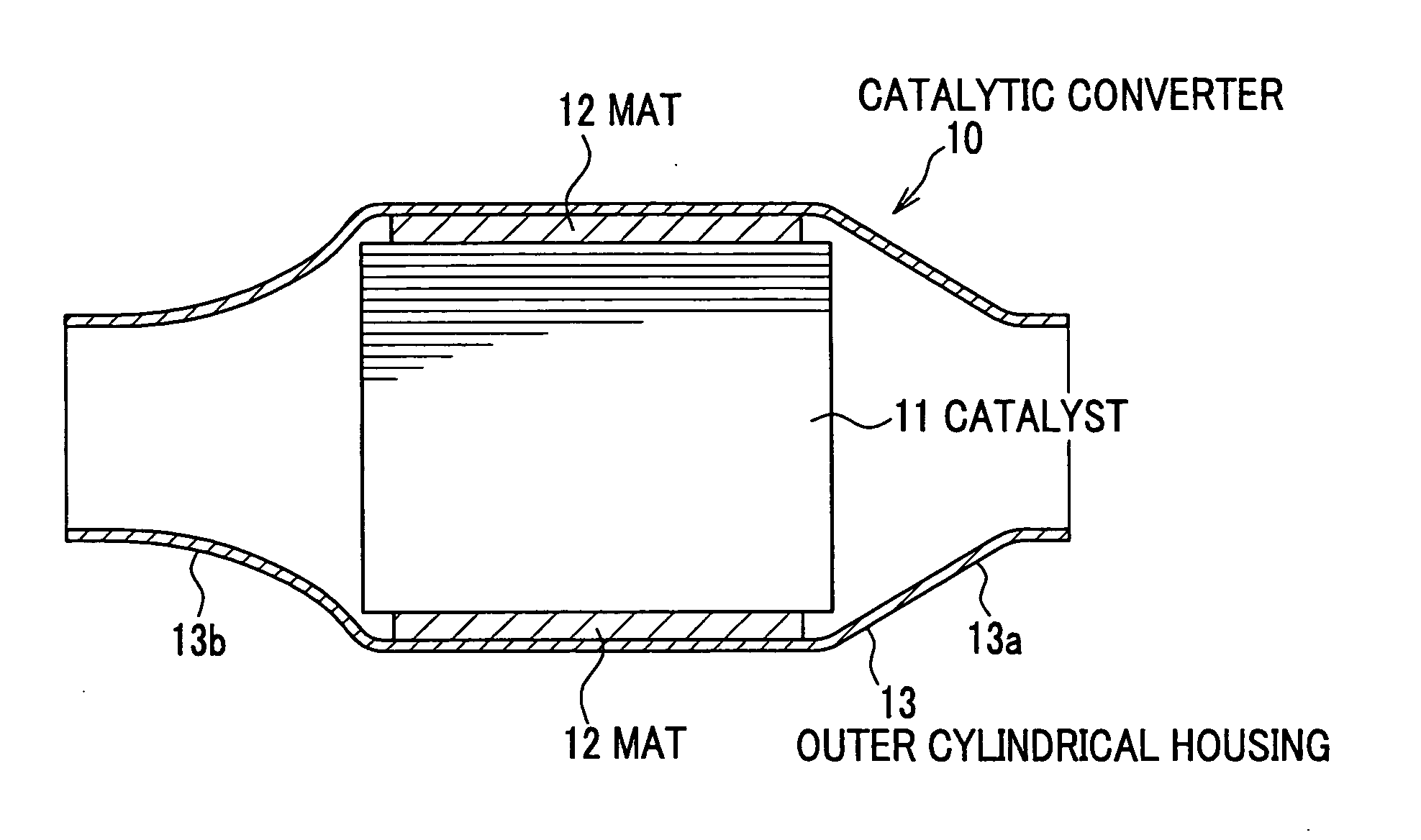
a technology of catalytic converters and manufacturing methods, which is applied in the direction of physical/chemical process catalysts, lighting and heating apparatus, separation processes, etc., can solve the problem of inability to have the same surface pressure on the mat, and achieve excellent detection efficiency and cost reduction

Inactive Publication Date: 2007-09-13
HIROTEC CORP
View PDF4 Cites 17 Cited by
  • Summary
  • Abstract
  • Description
  • Claims
  • Application Information

AI Technical Summary

Benefits of technology

[0011] In view of the above, the object of the present invention is to provide a method of manufacturing a catalytic converter, a catalytic converter, and a method of controlling catalytic converters, which can provide an identical surface pressure of mats, and which can stably support the catalyst, and further which can improve the productivity. MEANS FOR SOLVING THE PROBLEMS
[0058] According to these controlling methods, since the outer surface of the mat is covered by the sheet, it is possible to prevent an occurrence of dispersion in friction coefficient upon detecting the pressing force because of adhesion of the binder contained in the mat. Further, since the mat to which the sheet is attached is hardly affected by moisture, the detection of the pressing force can be performed in a more stable manner. The determination as to whether or not the catalyst is supported by the predetermined mat packing density can also be made in a more stable manner without dispersion in friction coefficient.

Problems solved by technology

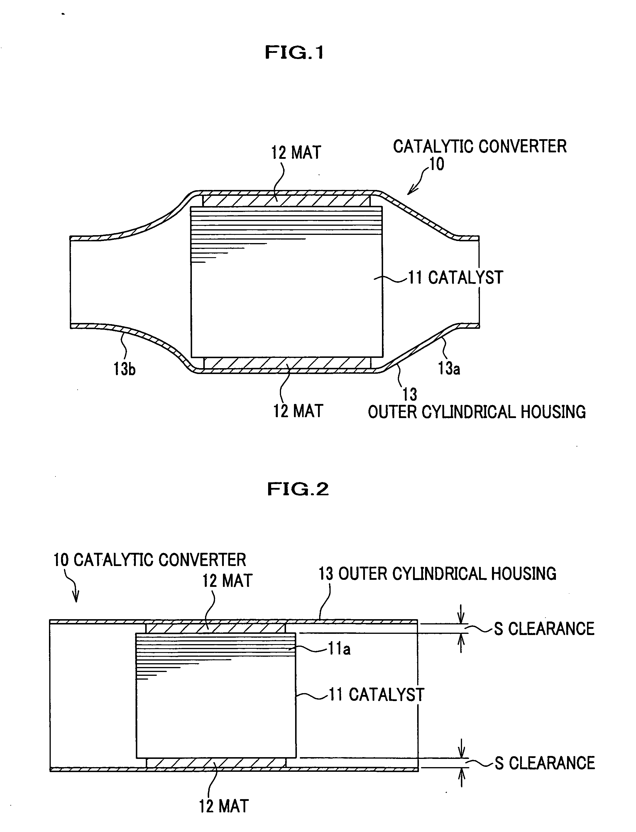
However, since catalysts differ in outer diameter size among the respective products, if the outer cylindrical housings are processed to have the same diameter by the swaging process, it is impossible for the mats to have the identical surface pressure.

Method used


Image

  • Method Of Manufacturing Catalytic Converters, Catalytic Converters, And Method Of Controlling Catalytic Converters
  • Method Of Manufacturing Catalytic Converters, Catalytic Converters, And Method Of Controlling Catalytic Converters
  • Method Of Manufacturing Catalytic Converters, Catalytic Converters, And Method Of Controlling Catalytic Converters

Examples


example

[0148] An example according to the present invention will be described below.

[0149] As catalysts to be used, columnar honeycomb-shaped ceramic catalysts were prepared, each of which was 118 mm in length and 118.4 mm (actual measurement values: φ117.1-119.7 mm) in outer diameter. As mats used for these catalysts, mat materials prepared from alumina fibers using binder were prepared.

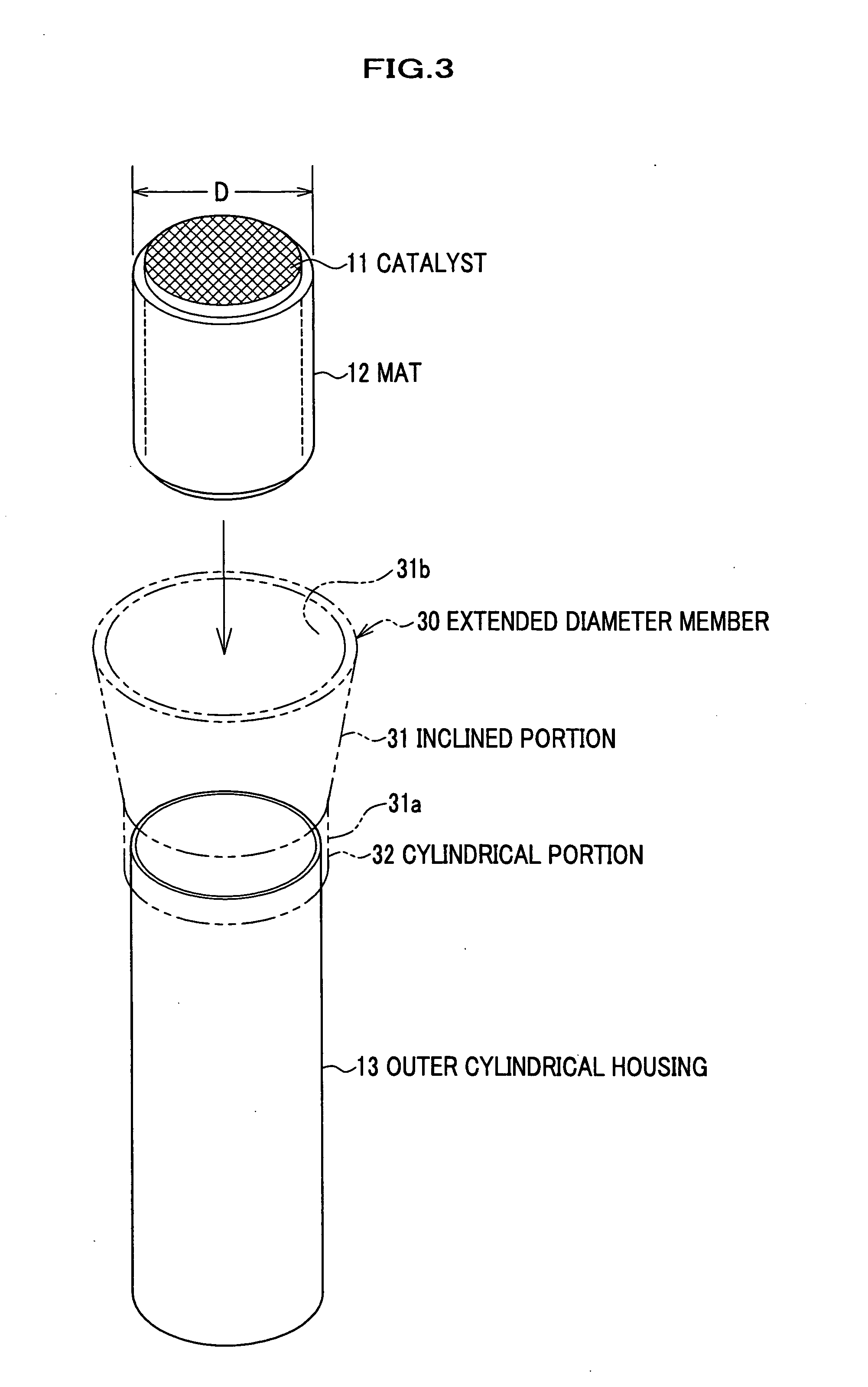
[0150] The catalyst around which the mat had been wrapped was press-fitted into the outer cylindrical housing the funnel-shaped enlarged diameter member, and the counterforce in accordance with this pressing force was detected by the load cell, to thereby measure the pressing force upon press-fitting. FIG. 15 is a graph showing the relation between measurement value (eighteen samples) of the pressing force (kN) of the catalyst having 118 mm length and target outer diameter (mm). As shown by the solid line in the figure, the relation between pressing force (kN) and target outer diameter (mm) was obtained ...


PUM

PropertyMeasurementUnit
lengthaaaaaaaaaa
lengthaaaaaaaaaa
packing densityaaaaaaaaaa

Abstract

A method of manufacturing a catalytic converter includes the steps of: a detecting step for detecting a pressing force at a time when a catalyst (11) is press-fitted into an outer cylindrical housing (13); a calculating step for calculating a diameter reduction, by which a clearance value between the outer cylindrical housing (13) and the catalyst (11) is set to a desired target value, based on the pressing force detected by the detecting step; and a swaging step for reducing a diameter of the outer cylindrical housing (13) based on the diameter reduction calculated by the calculating step.

Description

TECHNICAL FIELD [0001] The present invention relates to methods of manufacturing catalytic converters, catalytic converters, and methods of controlling catalytic converters, wherein each catalytic converter contains a catalyst wrapped with a cushion mat and supported in an outer cylindrical housing. BACKGROUND OF THE INVENTION [0002] Conventionally, exhaust systems of various engine types including automobile engines have been provided with a catalytic converter for cleaning exhaust gases. In general, a catalytic converter basically includes a columnar catalyst, a mat to be wrapped around the catalyst, and an outer cylindrical housing for accommodating the catalyst around which the mat has been wrapped, and by reducing the diameter (swaging) of the outer cylindrical housing the mat is pressed so that the catalyst is supported in the outer cylindrical housing. [0003] The mat to be wrapped around the catalyst is made of heat resisting fibrous material and interposed between the cataly...

Claims


Application Information

Patent Timeline
Patent Type & Authority Applications(United States)
IPC IPC(8): B01D53/34B01D53/86B01J33/00F01N3/28
CPCB23P11/005B23P2700/03Y10T29/49345F01N2450/02F01N3/2853F01N3/28B01J33/00F01N3/24
Inventor KOBAYASHI, NAOYUKIKOSAKA, ETSUOTANIGAWA, KAZUO
Owner HIROTEC CORP
Learn More