
Overheat Protection Device and Electrical System Having Same

a protection device and protection device technology, applied in the direction of secondary cells servicing/maintenance, cell components, electrochemical generators, etc., can solve the problems of abnormal heating, joule heat is considerably generated, temperature anomaly, etc., and achieve the effect of effective prevention of an electrical system and reduction of the power efficiency of the electrical system

Inactive Publication Date: 2007-09-13
LITTELFUSE JAPAN GK
View PDF13 Cites 23 Cited by
  • Summary
  • Abstract
  • Description
  • Claims
  • Application Information

AI Technical Summary

Benefits of technology

[0036] According to the present invention, there is provided a novel overheat protection device which can effectively prevent an electrical system (e.g. one comprising a secondary battery) from overheating by interrupting a current flowing through the electrical system depending on a temperature of the electrical system, and the electrical system including the same. According to the overheat protection device and / or the electrical system of the present invention, unlike in the conventional case in which a PTC element only functions to detect a thermal anomaly and restrict the current flowing through the electrical system, the variable resistive element such as a PTC element functions to detect the temperature anomaly, and to control the current flowing through the electrical system with the switching element, and therefore the decrease in the power efficiency of the electrical system can be made as small as a negligible degree.
[0037] Further, when plural variable resistive elements are used in the present invention, the plural variable resistive elements can be mounted on various positions of the electrical system, and therefore the temperature anomaly of the electrical system can be detected more promptly so that this is preferable to address occurrence of a localized temperature anomaly, as compared with a case of using one variable resistive element.

Problems solved by technology

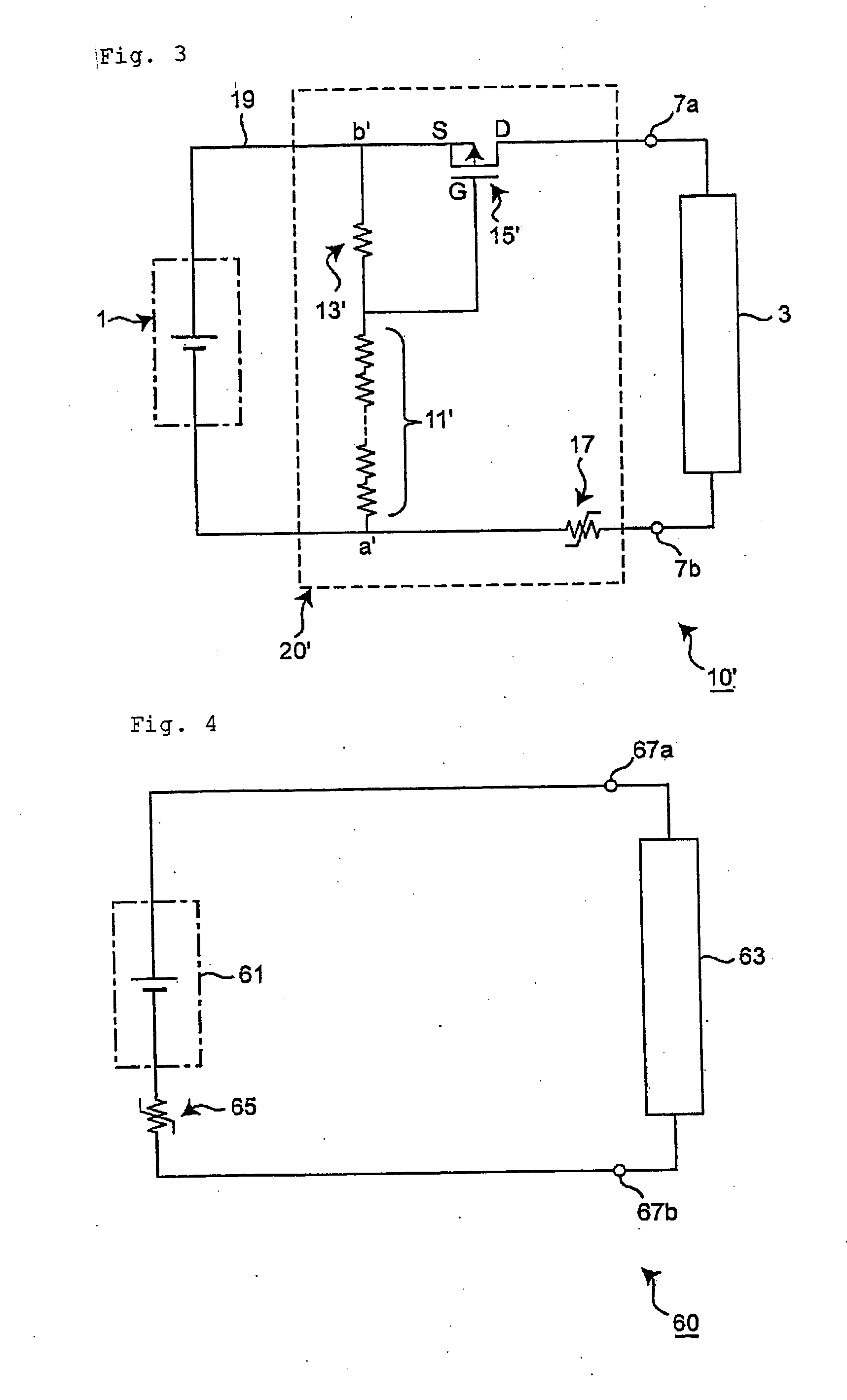
However, it may be assumed that the discharge reaction in the secondary battery 61 excessively proceeds to cause a temperature anomaly (abnormal heating).
However, if the current flowing through the electric circuit 60 becomes too large, Joule heat is considerably generated in the PTC element 65.

Method used


Image

  • Overheat Protection Device and Electrical System Having Same
  • Overheat Protection Device and Electrical System Having Same
  • Overheat Protection Device and Electrical System Having Same

Examples


Embodiment Construction

[0052] An overheat protection device and an electrical system (not shown) including it in one embodiment of the present invention is hereinafter described.

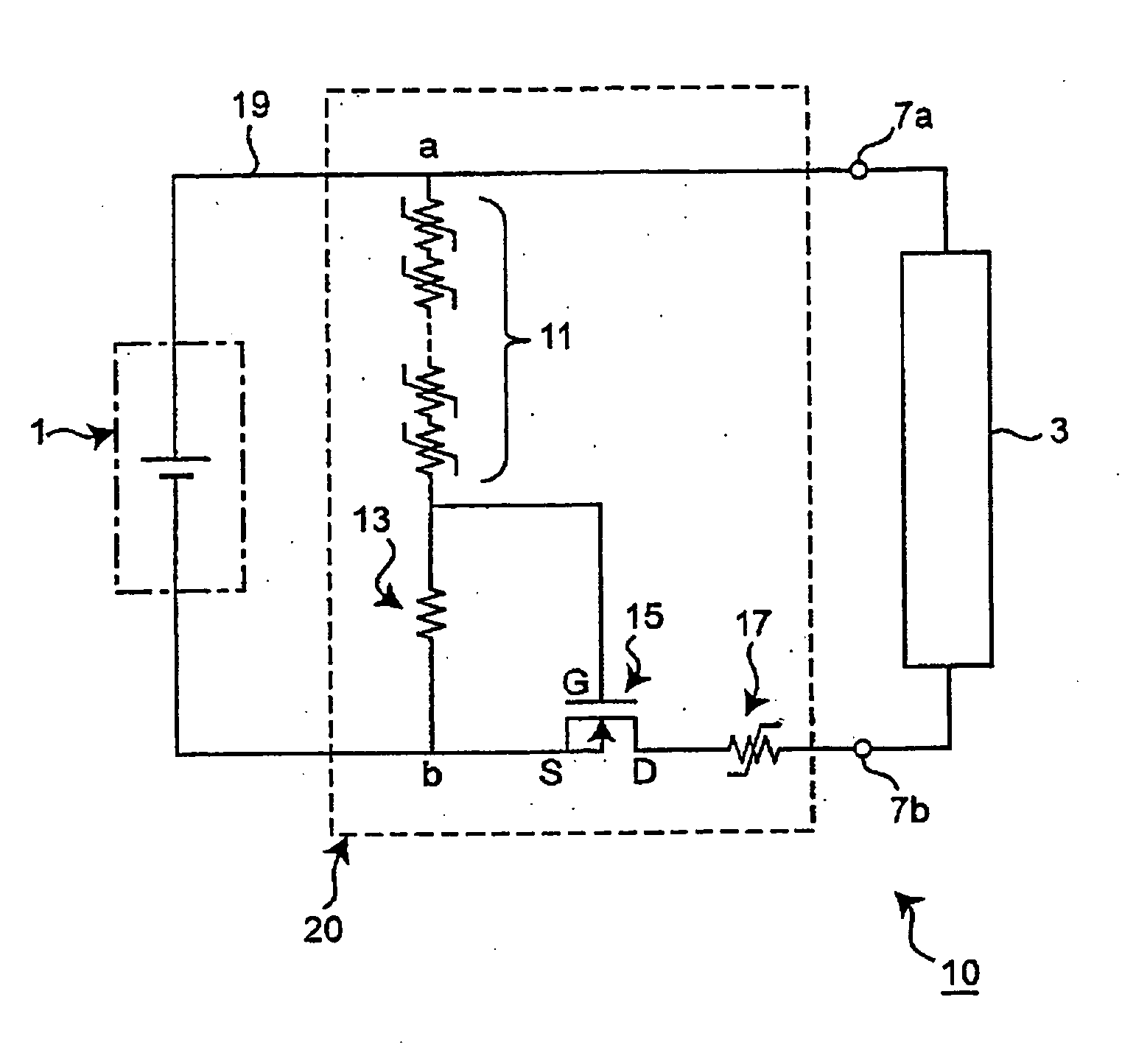
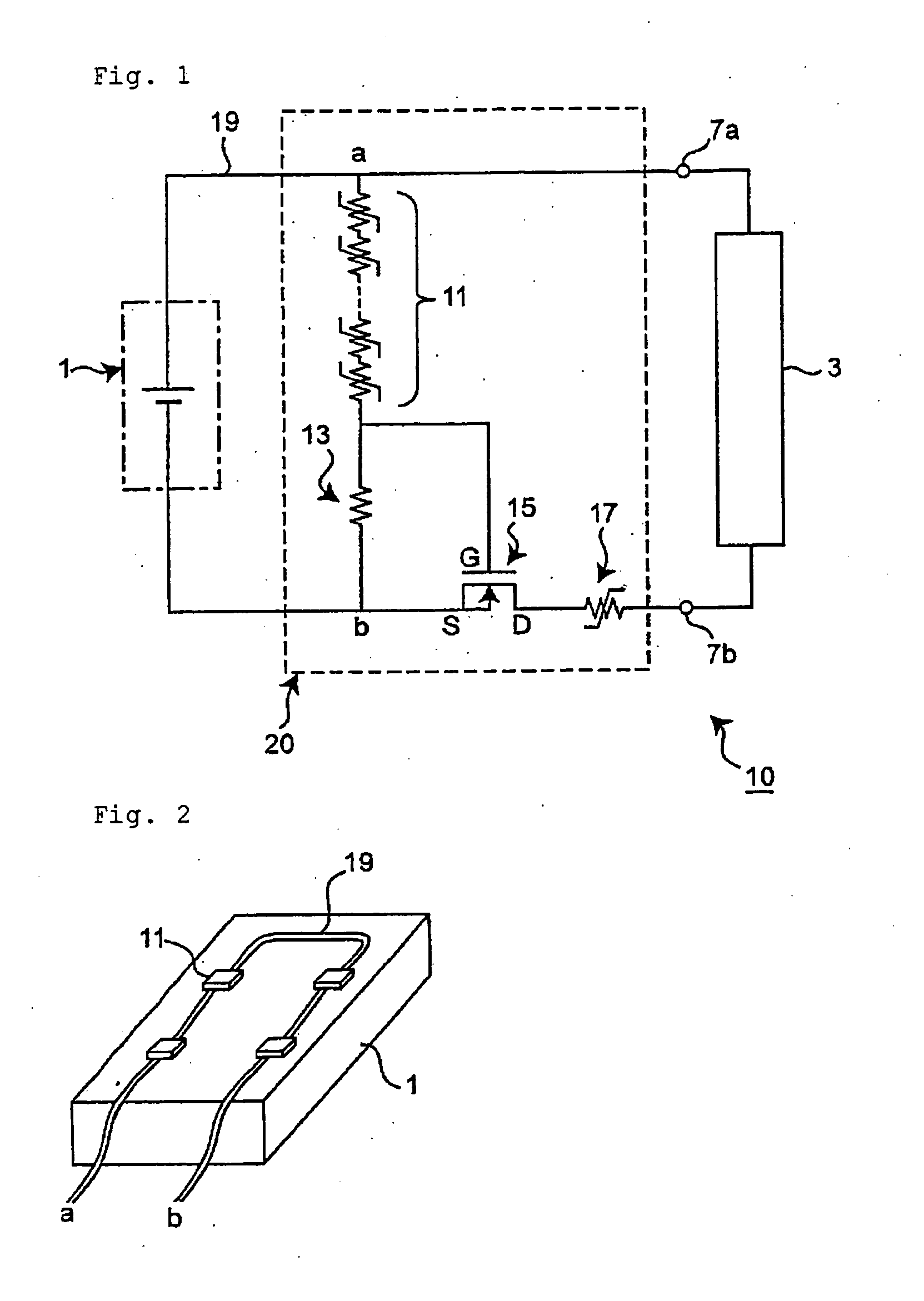
[0053]FIG. 1 shows a diagram of an electric circuit 10 incorporating an overheat protection device 20 of this embodiment. In general, as shown in FIG. 1, a secondary battery 1 is electrically connected to an application circuit (en electrical element) 3 via terminals 7a and 7b with wiring 19 to form the electric circuit 10. In this electric circuit 10, the overheat protection device 20 (a part surrounded by the dotted line in the drawings) is electrically connected in parallel to and between the secondary battery 1 and the application circuit 3. The electrical system of this embodiment (not shown) is a left part with respect to the terminals 7a and 7b, which is provided with the secondary battery 1 and the overheat protection device 20 and corresponds to a so-called battery pack. The application circuit 3 is detachable from the e...


PUM


Abstract

The present invention provides an overheat protection device which is capable of effectively preventing a secondary battery from overheating. In the overheat protection device (20), a variable resistive element(s) (11) of which resistance varies depending on a temperature is located on and thermally combined with a certain position(s) of an electrical system (1), and a switching element (15) for controlling a current depending on an applied voltage thereto is arranged so as to control the current flowing through the electrical system (1). When the certain position of the electrical system (1) comes to be under a high temperature condition, the variable resistive element (11) interrupts the current flowing through the electrical system (1) by changing the applied voltage to the switching element (15).

Description

TECHNICAL FIELD [0001] The present invention relates to an overheat protection device for preventing an electrical system or apparatus, e.g. a secondary battery, from overheating, and more specifically to the overheat protection device using a variable resistive element such as a PTC element of which resistance varies depending on a temperature. Further, the present invention relates to the electrical system or apparatus having such overheat protection device. [0002] The term “PTC element” means a thermistor having a Positive Temperature Coefficient, as is known in the field of the electric / electronic circuit technology. When a temperature of the PTC element is relatively low (e.g., an ordinary or room temperature), an electric resistance thereof is also low, but when the temperature of the PTC element exceeds a certain temperature (hereinafter referred to as a trip temperature), the electric resistance steeply increases. Throughout the present description, the former state of the P...

Claims


Application Information

Patent Timeline
IPC IPC(8): H01C3/04H01M10/50H01M10/42H01M50/574H02H5/04H02H7/18
CPCH01M2/34H01M2/348H02H7/18H02H5/042H01M10/42Y02E60/10H01M50/581H01M50/574H02H5/04
Inventor HASUNUMA, TAKASHISATO, TAKASHI
Owner LITTELFUSE JAPAN GK
Learn More