
Method and system for transmitting/receiving data in a communication system

a communication system and data technology, applied in the field of communication systems, can solve the problems of inefficient uplink scheduling, data transmission not using all allocated resources, and inability to meet the needs of mobile stations, so as to reduce overhead information, reduce overhead information, and efficiently allocate resources

Inactive Publication Date: 2007-09-06
SAMSUNG ELECTRONICS CO LTD
View PDF12 Cites 160 Cited by
  • Summary
  • Abstract
  • Description
  • Claims
  • Application Information

AI Technical Summary

Benefits of technology

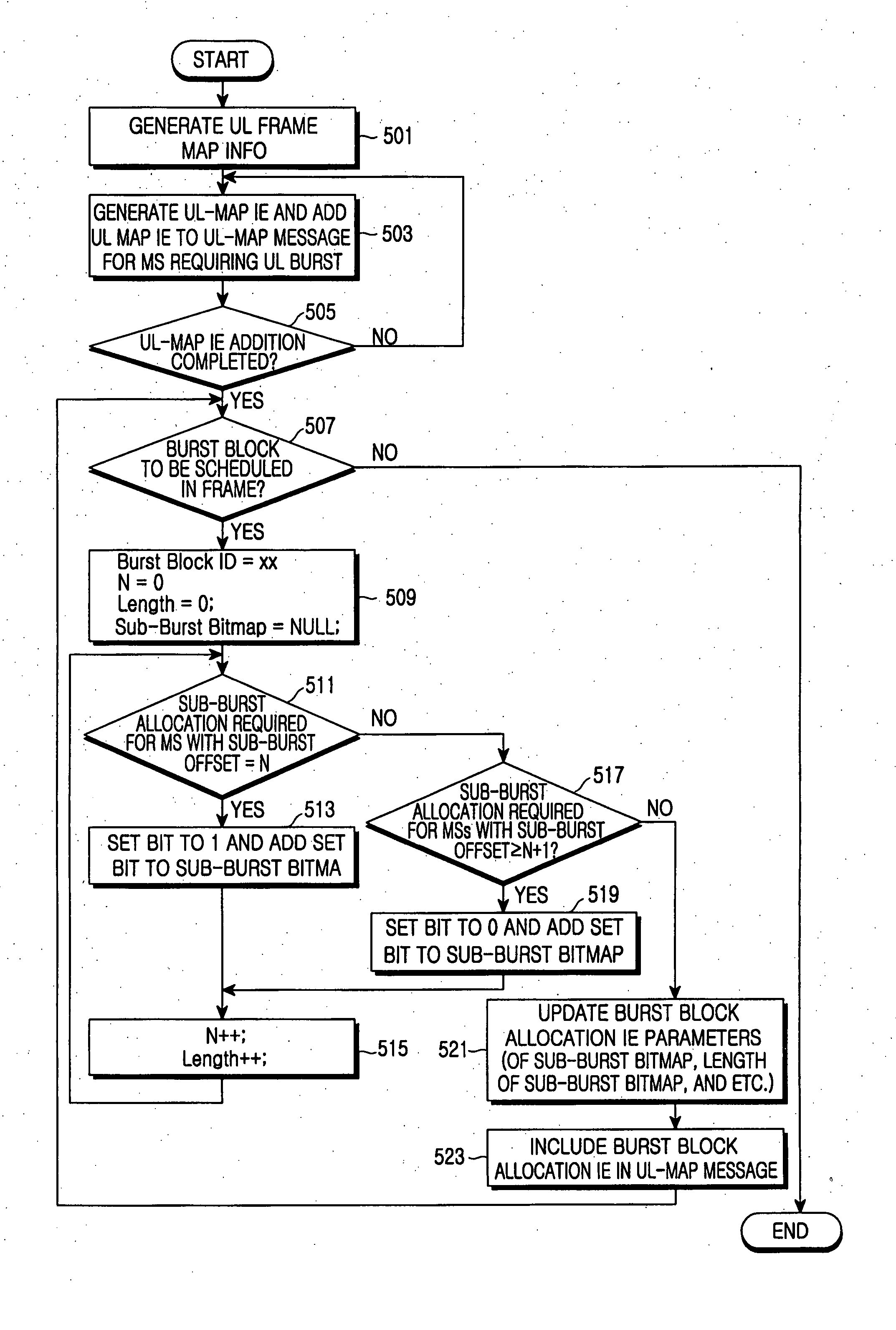
The present invention provides a method and system for efficiently transmitting and receiving data in a communication system. The method involves grouping mobile stations using a real-time service into groups, allocating burst blocks to the groups, and allocating data bursts of burst blocks to the mobile stations. The mobile stations determine whether their own uplink burst is allocated and transmit data to the base station through a sub-burst of a burst block allocated to their group. The system includes a base station for grouping mobile stations, allocating burst blocks, and allocating data bursts, and a mobile station for determining whether its own uplink burst is allocated and transmitting data to the base station through a sub-burst of a burst block allocated to its group. The technical effects of the invention include efficient allocation of resources, reduction of overhead information, and reduction of sub-burst allocation for mobile stations.

Problems solved by technology

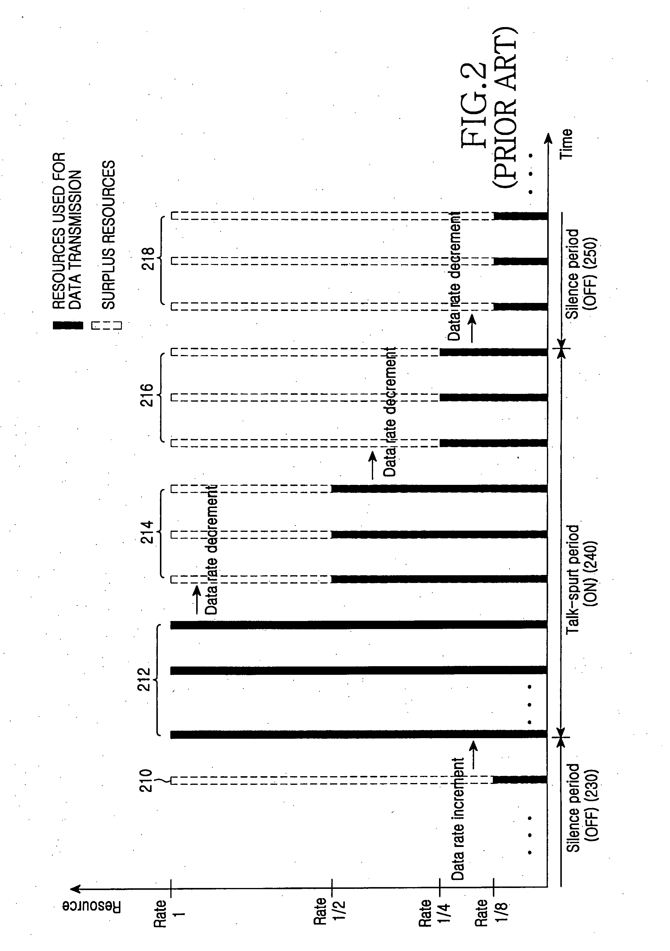
However, the MS does not use all the allocated resources to transmit data.
The presence of the surplus resources implies inefficient uplink scheduling.
Thus, there is a problem in that uplink resources may be wasted in the talk-spurt periods as well as in the silence periods.
There is a problem in that a 32-bit UL-MAP IE should be provided to transmit a small amount of data in terms of an amount of UGS data to be transmitted from the MS and overhead for signaling uplink resource allocation.
Thus, there is a problem in that an unnecessary polling process leads to a waste of uplink resources.
There is a problem in that a 32-bit UL-MAP IE should be included in the UL-MAP message to periodically allocate fixed uplink resources for the BW request header of the MS as described with reference to the UGS.

Method used


Image

  • Method and system for transmitting/receiving data in a communication system
  • Method and system for transmitting/receiving data in a communication system
  • Method and system for transmitting/receiving data in a communication system

Examples


Embodiment Construction

[0074] Preferred embodiments of the present invention will be described in detail herein below with reference to the accompanying drawings. Descriptions of well-known functions and constructions are omitted for clarity and conciseness.

[0075] Terms or words used in the specification and the claims are not limited to conventional or dictionary definitions, but should be interpreted as meanings and concepts that conform to the technical spirit of the present invention, based on the principle that an inventor(s) can adequately define the concepts of words in order to explain the invention in the best way. The matters defined in the description, such as a detailed construction and elements, are provided to assist in a comprehensive understanding of preferred embodiments of the invention. Those of ordinary skill in the art will recognize that various equivalents and modifications of the embodiments described herein can be made at the time of filing the application.

[0076] The present inv...


PUM


Abstract

A method for transmitting and receiving data in a communication system. The method includes grouping, by a Base Station (BS), Mobile Stations (MSs) using a real-time service, into groups, allocating burst blocks to the groups, and allocating data bursts of burst blocks to the MSs; and determining, by each MS, whether its own uplink burst is allocated, and transmitting data to the BS through a sub-burst of a burst block allocated to a group to which each MS belongs.

Description

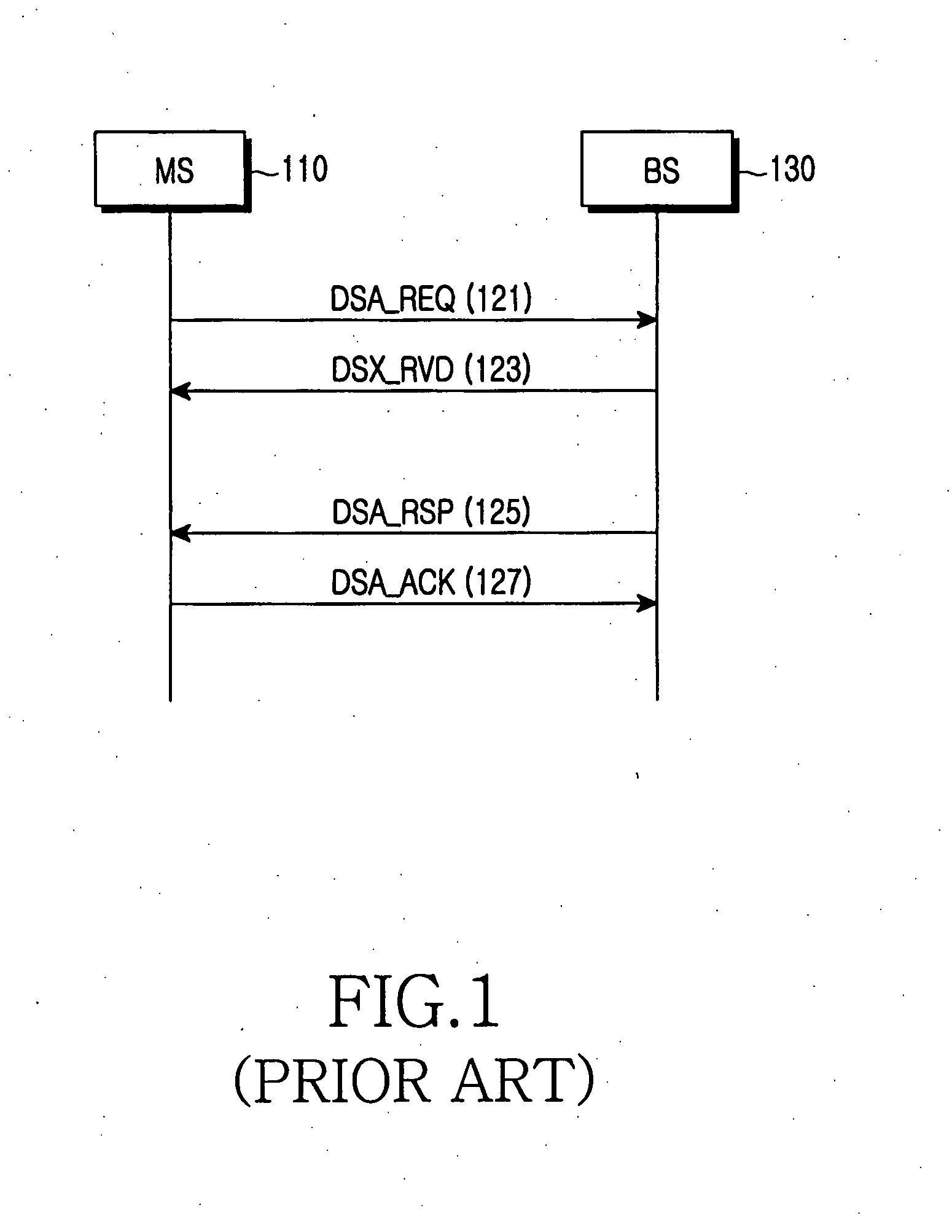
PRIORITY [0001] This application claims the benefit under 35 U.S.C. § 119(a) of a Korean Patent Application filed in the Korean Intellectual Property Office on Feb. 8, 2006 and assigned Serial No. 2006-12151, the disclosure of which is incorporated herein by reference. BACKGROUND OF THE INVENTION [0002] 1. Field of the Invention [0003] The present invention generally relates to a communication system, and more particularly to a method and system for transmitting / receiving data in a communication system. [0004] 2. Description of the Related Art [0005] Communication systems provide services using limited resources. In order to provide various services using limited resources, wireless systems use a scheduling scheme for efficiently employing resources. A conventional communication method between a Base Station (BS) and a Mobile Station (MS) used in the scheduling scheme will now be described. [0006] The BS provides the MS using uplink resource allocation with control information inclu...

Claims


Application Information

Patent Timeline
Patent Type & Authority Applications(United States)
IPC IPC(8): H04J3/16
CPCH04L27/2608H04W72/048H04W72/042H04L5/0044H04W72/51H04W72/23H04W72/0446H04L1/0009
Inventor SON, YEONG-MOONJOO, PAN-YUHSON, JUNG-JECHO, JAE-WEONLEE, SUNG-JINKANG, HYUN-JEONGHONG, SONG-NAMLEE, MI-HYUNLIM, HYOUNG-KYUKIM, YOUNG-HO
Owner SAMSUNG ELECTRONICS CO LTD
Learn More