
Solar air heater

Active Publication Date: 2007-08-30
DOHERTY PAUL M
View PDF44 Cites 33 Cited by
  • Summary
  • Abstract
  • Description
  • Claims
  • Application Information

AI Technical Summary

Benefits of technology

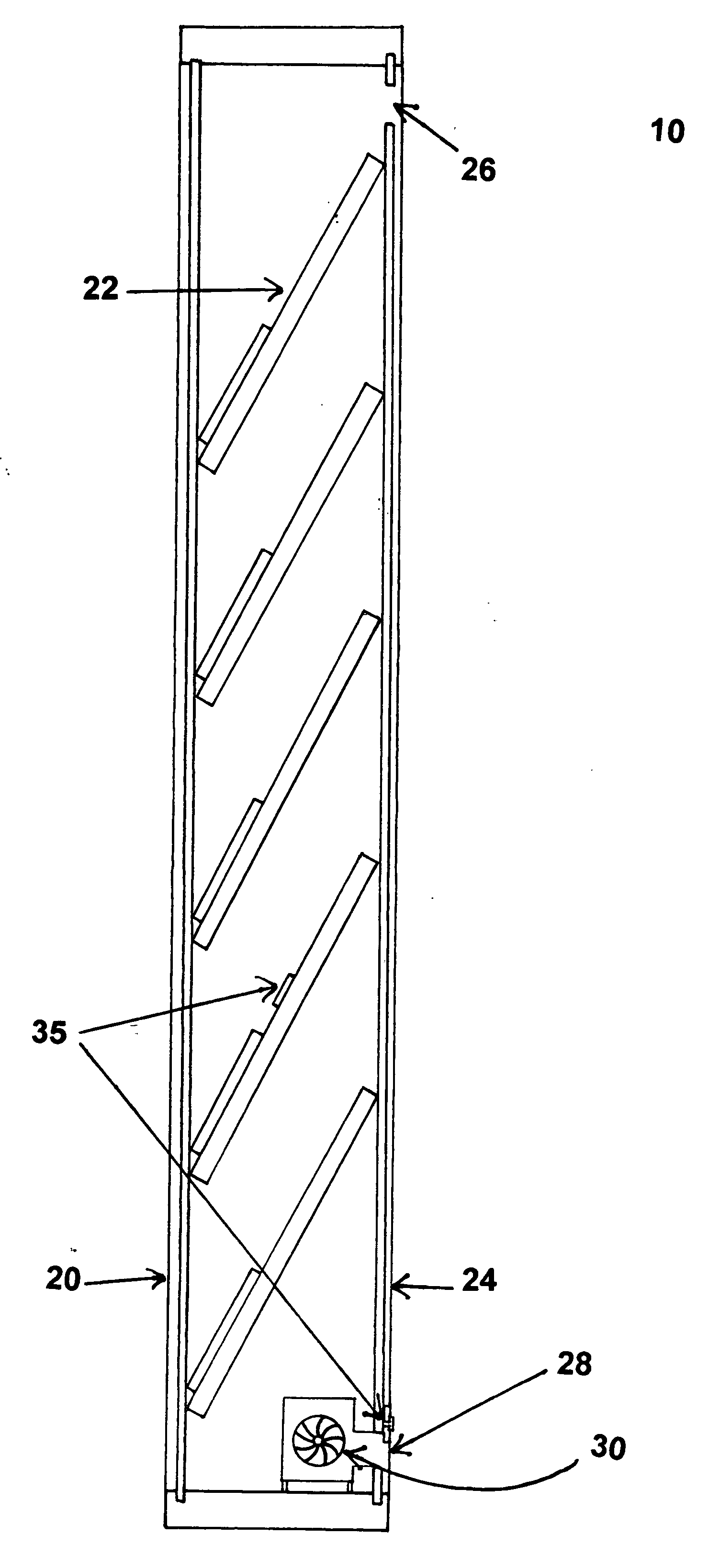
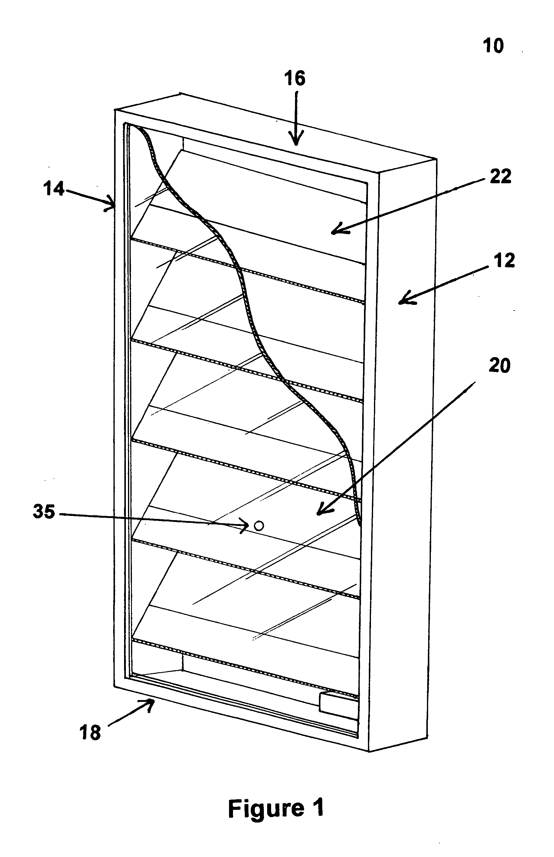
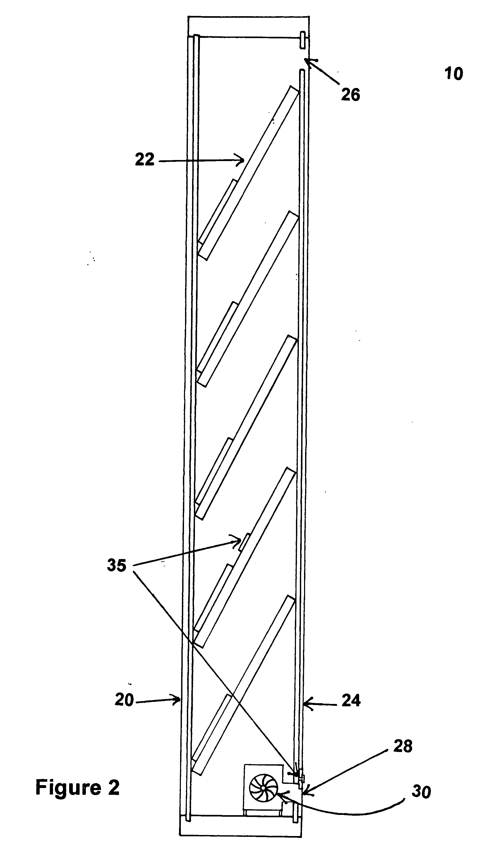
[0008] In one aspect, the invention relates to a solar air heater wherein the enclosed space within the device housing is divided into at least two essentially isolated sections by a partition. The partition(s) of the present invention solar air heater are parallel to each other and to the top and bottom panels of the enclosure. The partition(s) of the enclosure contact the side panels perpendicularly and contact the front and back panels at a non-perpendicular angle. Furthermore, the partitions of the present invention comprise a plurality of channels allowing adjacent sections to be in fluid communication with each other. The channels are small enough in diameter to prevent any significant back flow of air. This design not only solves the prior art problem of incoming cold air

Problems solved by technology

Still, prior art devices are not as efficient as homeowners or other building owners would like.
Such mixing decreases the average temperature of the air in the heater and, thus, reduces the overall efficiency of the heater.
Many homes may not have such an expanse of wall space conveniently located for both best sun exposure and best room air exchange.
Still, this device has the problem of a reduced average temperature since it also permits the mixing of incoming cold air with the warm air in the device.
This design of McCullough, although an improvement over other prior art designs, only minimizes the mixing of cold incoming air with heated air.
Since the system is not designed to ensure positive pressure evenly over the entire surface of the vertical porous panel nor reduce or eliminate airflow eddies, the system permits the back flow of air through the vertical porous panel resulting in loss of efficiency by the heater.
However, all of the prior art solar air heaters known by the Inventor fail to address the problem of cold incoming air mixing with heated air.

Method used


Image

  • Solar air heater
  • Solar air heater
  • Solar air heater

Examples


example 1

[0038] This example shows the ability of the solar air heater of the present invention to generate heated air.

[0039] In this example, the solar air heater of the present invention was operated over a period of 24 hours. The ambient room temperature for the period in which the solar air heater of the present invention was operated varied between a low of 43.3° F. before the heater was used to a high of 63.3° F. after operation of the heater. The room was subject to no other heating devices. The graph in FIG. 5 shows the temperature of the air within the solar air heater of the present invention over a period of 24 hours in ° F. Once the heater was exposed to solar radiant energy the temperature of the air within the heater increased to 133° F. The fan of the heater was set to turn on at 130° F. The temperature of the heater increased three more degrees after the fan turned on until cool room air entered into the heater in sufficient quantities to lower the internal air temperature o...


PUM


Abstract

This invention provides novel devices and methods for the heating of air with solar radiant energy. The devices of the present invention feature a housing partitioned into essentially isolated sections wherein the sections are in fluid communication with each other through a plurality of channels located within the partitions. The two unique features of the invention, essentially isolated sections and partitions comprising a plurality of channels, increase the temperature achieved by the solar heater by 1) creating multiple, sequential sections that function independently of each other providing a higher starting temperature in each section and, therefore, a higher final temperature, 2) providing second means of heating the air within the channels located within the partitions and, 3) by virtually eliminating the mixing of incoming cold air with the heated air of the solar air heater.

Description

BACKGROUND OF INVENTION [0001] The invention relates generally to solar air heaters. Most solar air heaters work on the same principle as a greenhouse wherein sunlight is converted to heat within a glass or plastic covered enclosure. The heat is then trapped in the enclosure by the glass or plastic. Solar heating is an economical way for persons to augment the heating of homes and other buildings. The devices can be economical to build or buy and energy from the sun is free. Still, prior art devices are not as efficient as homeowners or other building owners would like. The reason for this, at least in part, is because cold incoming air is allowed to mix with the heated air in the solar air heater. Such mixing decreases the average temperature of the air in the heater and, thus, reduces the overall efficiency of the heater. [0002] Prior art solar air heaters have tried to increase efficiency by one or more of, for example, increasing the size of the heater, increasing the surface ar...

Claims


Application Information

Patent Timeline
IPC IPC(8): F24J2/04F24S10/70F24S20/30
CPCF24J2/202F24J2/22Y02E10/44Y02B10/20F24J2/402F24S10/55F24S50/40F24S10/502
Inventor DOHERTY, PAUL M.
Owner DOHERTY PAUL M
Learn More