Apparatus and methods relating to spatially light modulated microscopy

a spatial light and microscopy technology, applied in the field of microscopy, can solve the problems of increasing imaging speed, degrading resolution, slowing down conventional confocal microscopes to acquire images for certain applications, etc., and achieves selective control of illumination angle and enhanced imaging speed

Inactive Publication Date: 2007-08-16
MOTIC CHINA GRP CO LTD
View PDF18 Cites 18 Cited by
  • Summary
  • Abstract
  • Description
  • Claims
  • Application Information

AI Technical Summary

Benefits of technology

[0008] The present invention provides microscopes that have significant advantages in controlling the light that contacts a sample and / or that is detected emanating from a sample. The improved control includes enhanced, selective control of the angle of illumination, the quantity of light and the location of light reaching the sample and / or detector. The present invention provides these advantages by placing one or more spatial light modulators in the illumination and / or detection light path of the microscope at one or both of the conjugate image plane of the aperture diaphragm of the objective lens and the conjugate image plane of the sample.

Problems solved by technology

Still other known confocal scanning systems have used a laser beam rastered with rotating mirrors to scan a specimen or a laser beam that scans a slit rather than a spot; such slit scanning increases imaging speed but slightly degrades resolution.
Conventional confocal microscopes can be slow to acquire images for certain applications and become even slower as the scan line density increases and the aperture separation decreases.
In addition, it is difficult to practically adjust the perimeters of the confocal microscope in commercial systems, and the signal to noise ratio (SNR) is sacrificed to increase the imaging rate.
In addition, proper alignment of conventional confocal systems can be critical and difficult to maintain.
In addition, laser-based systems are more expensive than white light systems, but such laser systems do not offer a selection of illumination wavelengths and can also lead to photo toxicity and rapid photo bleaching.

Method used


Image

  • Apparatus and methods relating to spatially light modulated microscopy
  • Apparatus and methods relating to spatially light modulated microscopy
  • Apparatus and methods relating to spatially light modulated microscopy

Examples


Embodiment Construction

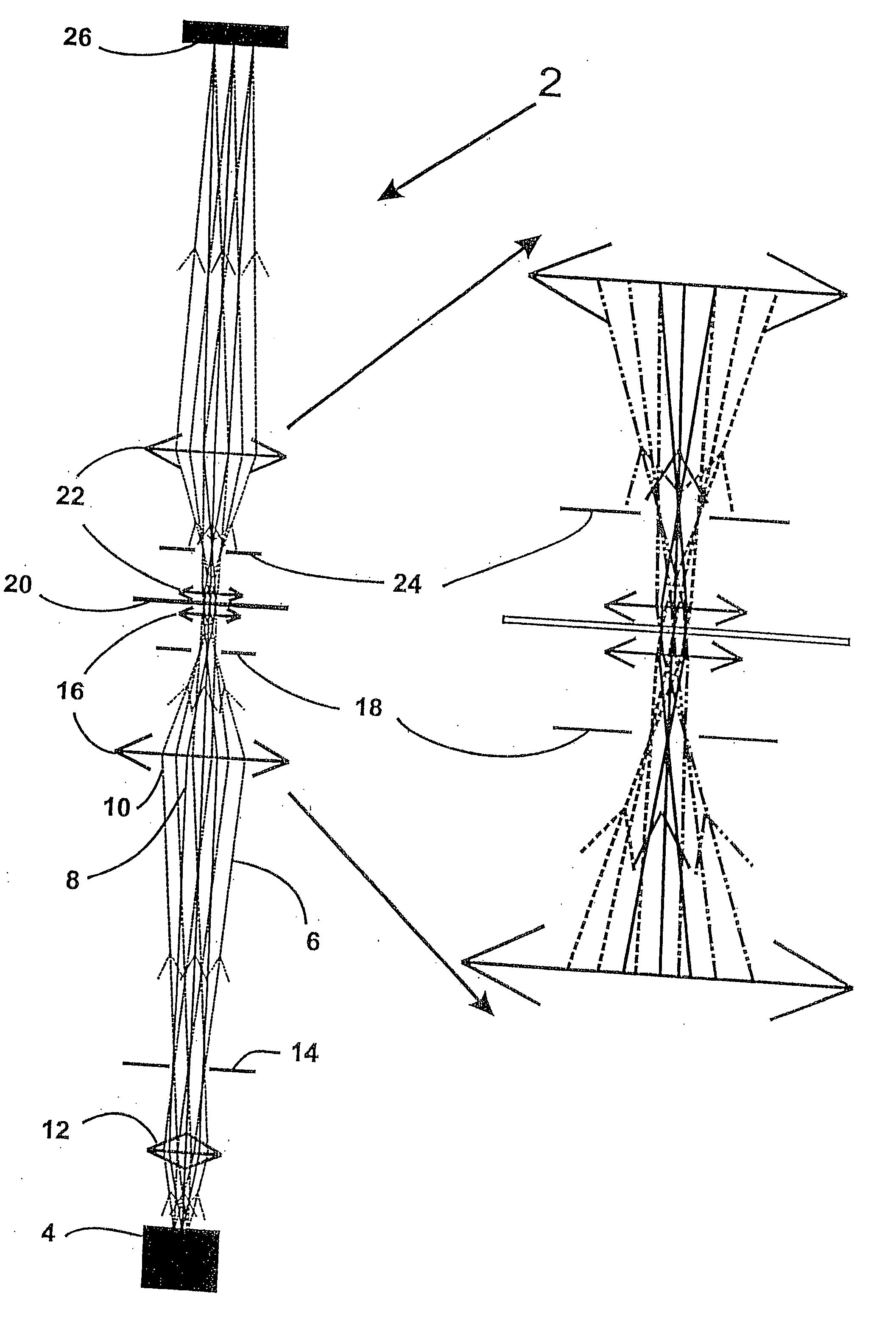
[0067] The present invention provides microscopes that have significant advantages in controlling the light that contacts the sample. The microscopes also have advantages with regard to the controlling the light that contacts a light detector, such as the eye of the user or a video camera. The improved control includes enhanced, selective control of the angle of illumination, quantity of light and location of light reaching the sample and / or detector, such that the light reaching the sample comprises one or more desired characteristics. The present invention provides these advantages by placing one or more spatial light modulators in the illumination and / or detection light path of the microscope at one or both of the conjugate image plane of the aperture diaphragm of the objective lens and the conjugate image plane of the sample.

[0068] Definitions

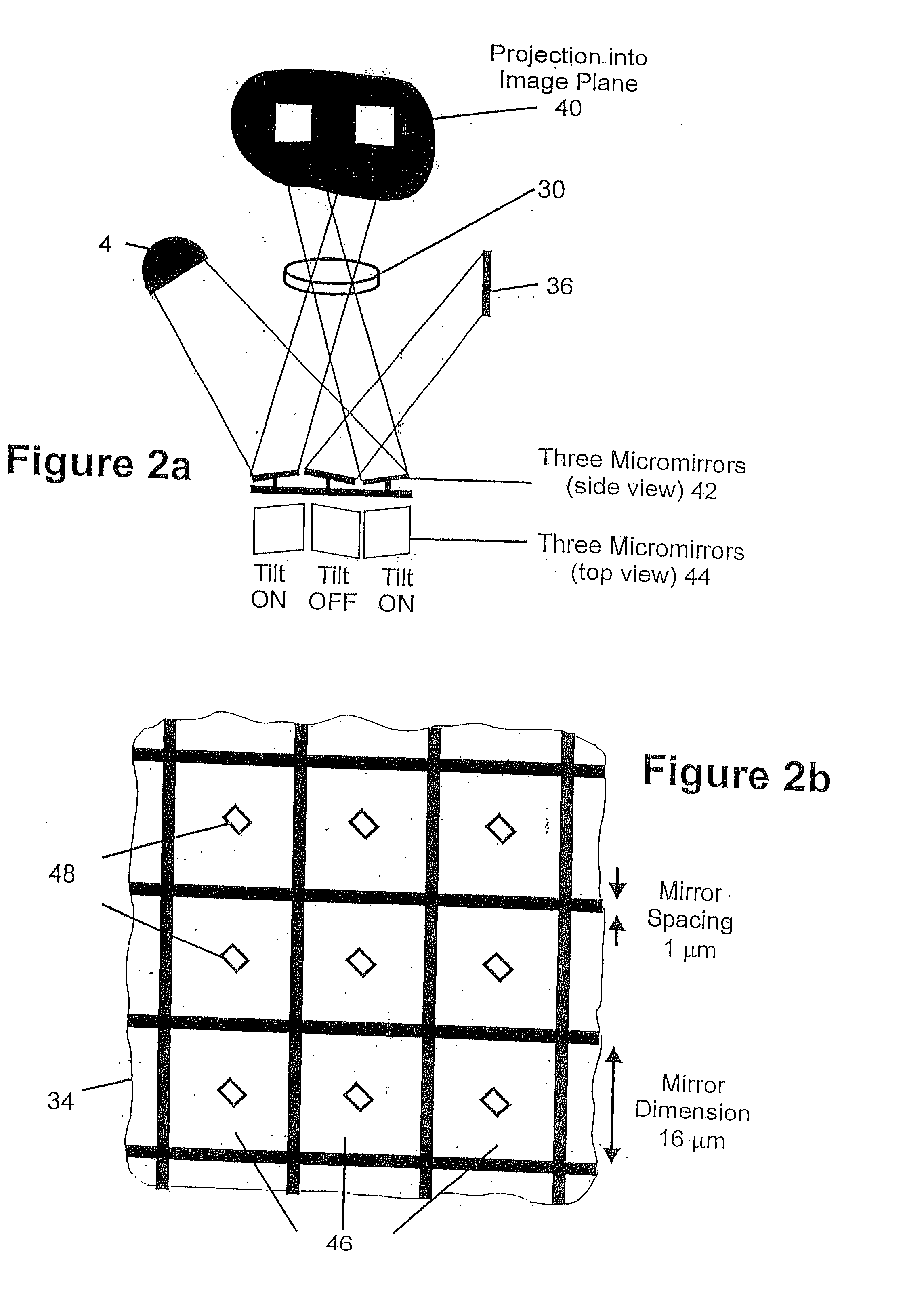
[0069] A “spatial light modulator” (SLM) is a device that is able to selectively modulate light. In the present invention, spatial light...


PUM

PropertyMeasurementUnit
cycle timeaaaaaaaaaa
timeaaaaaaaaaa
timeaaaaaaaaaa

Abstract

Apparatus and methods relating to microscopes having specific control of the light that contacts a sample and/or a light detector, such as the eye of the user, a charge couple device or a video camera. The improved control includes enhanced, selective control of the angle of illumination, quantity of light and location of light reaching the sample and/or detector. The microscopes comprise one or more spatial light modulators in the illumination and/or detection light path of the microscope at one or both of the conjugate image plane of the aperture diaphragm of the objective lens and the conjugate image plane of the sample.

Description

RELATED APPLICATIONS [0001] This application claims priority to U.S. Provisional Application No. 60 / 063,893 filed on Oct. 29, 1997, the contents of which are incorporated herein by reference.FIELD OF THE INVENTION [0002] The field of the present invention is the magnification of images of objects, and more particularly microscopes and the field of microscopy. BACKGROUND OF THE INVENTION [0003] Microscopy is used to produce magnified representations of both dynamic and stationary objects or samples. There are many different modes of microscopy such as brightfield microscopy, darkfield microscopy, phase contrast microscopy, fluorescence microscopy, reflectance or reflected light microscopy and confocal microscopy. All of these forms of microscopy deliver illumination light in a controlled, fashion to the sample and collect as much of the light containing the desired information about the sample as possible. Typically, this is accomplished using Kohler illumination in any of reflectanc...

Claims


Application Information

Patent Timeline
Patent Type & Authority Applications(United States)
IPC IPC(8): G02B21/06G01N21/27G01N21/64G02B21/00G02B21/10G02B21/12G02B21/16G02B21/36G02B26/08
CPCG02B21/006G02B21/0072Y10S359/90G02B21/36G02B26/0841G02B21/06
Inventor MACAULAY, CALUM E.
Owner MOTIC CHINA GRP CO LTD
Why Eureka
Try Eureka