
Circuit and method for loop control

a loop control and loop control technology, applied in the field of circuits and loop control methods, can solve the problems of increasing the size of instruction codes, inability to return, increasing the burden of users creating programs, etc., and achieve the effect of accurately evaluating a loop and accurately performing the loop end evaluation

Inactive Publication Date: 2007-08-09
RENESAS ELECTRONICS CORP
View PDF2 Cites 7 Cited by
  • Summary
  • Abstract
  • Description
  • Claims
  • Application Information

AI Technical Summary

Benefits of technology

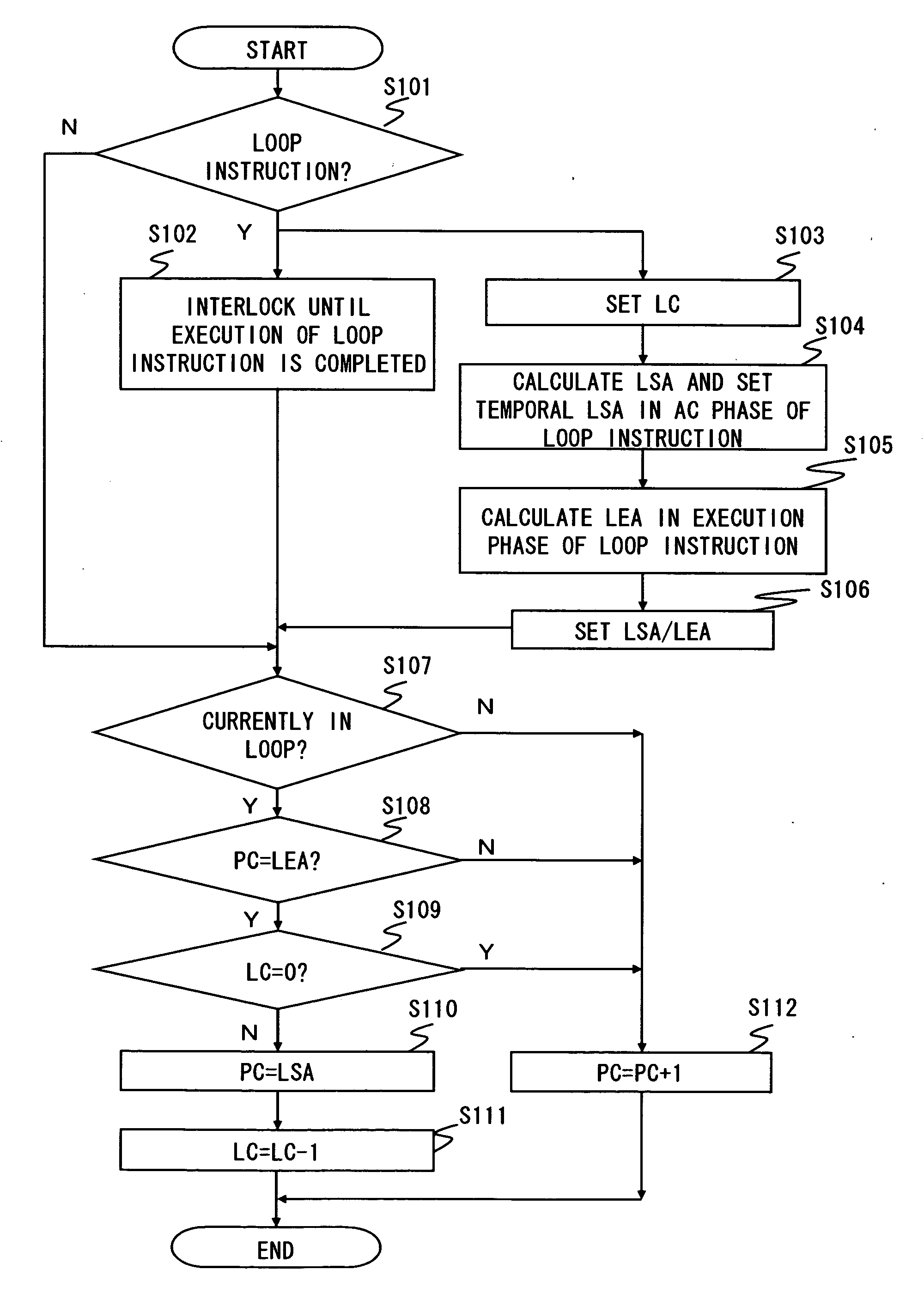
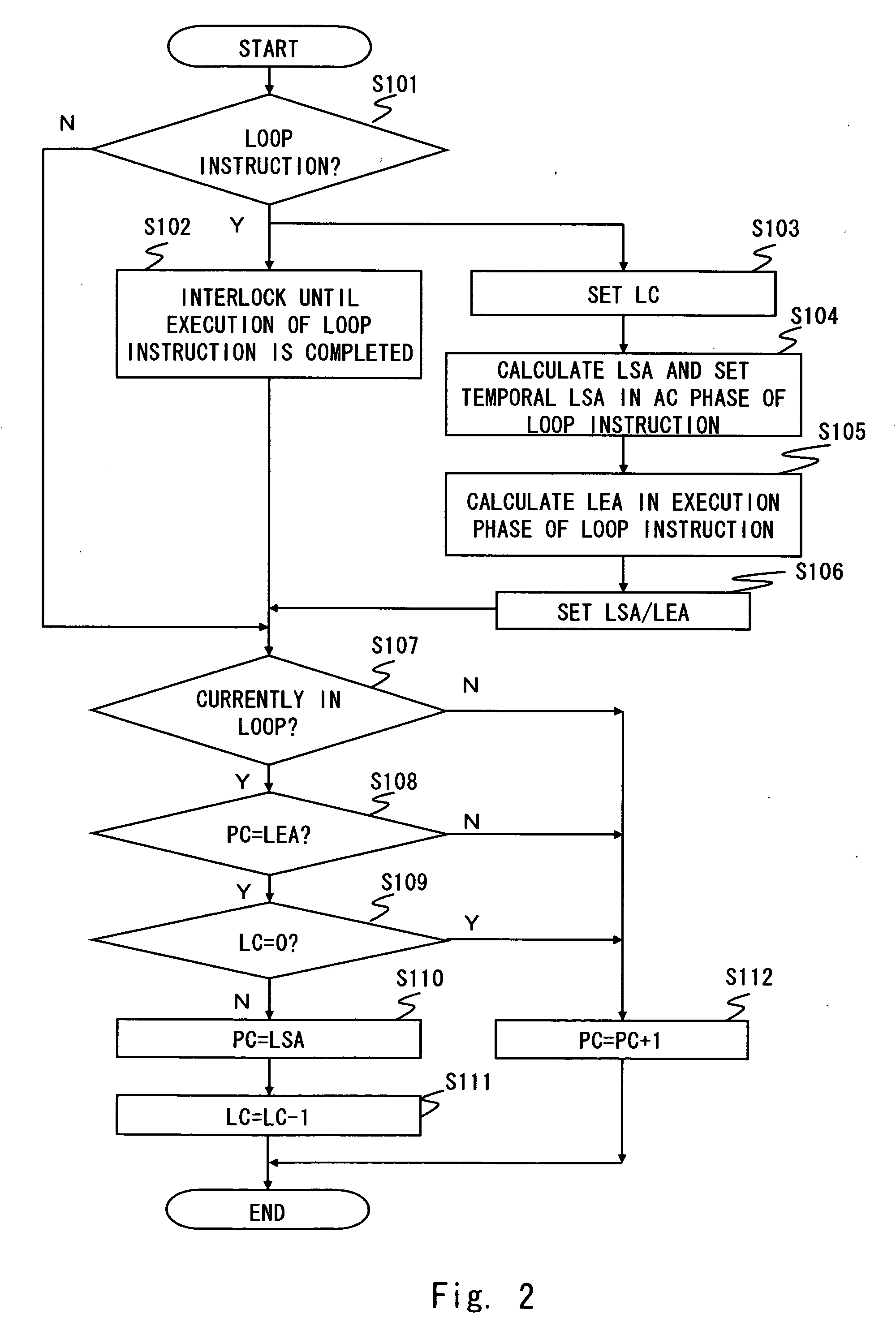
[0033]This loop control circuit generates an interlock until the execution of the loop instruction is completed. Thus the loop end evaluation can be performed after executing the loop instruction, thereby enabling to accurately perform the loop end evaluation.
[0035]This loop control circuit generates the interlock until the execution of the loop instruction is completed. Thus the loop end evaluation can be performed after executing the loop instruction, thereby enabling to accurately perform the loop end evaluation.
[0037]With this loop control method, the interlock is generated until the execution of the loop instruction is completed. Thus the loop end evaluation can be performed after executing the loop instruction, thereby enabling to accurately perform the loop end evaluation.
[0039]This loop control method generates the interlock until the execution of the loop instruction is completed. Thus the loop end evaluation can be performed after executing the loop instruction, thereby enabling to accurately perform the loop end evaluation.
[0040]The present invention provides a circuit and a method for loop control which are able to accurately evaluate a loop even with different pipeline configurations.

Problems solved by technology

Thus when the LEA is set, the next instruction in the instructions in the loop, which is the fourth instruction, is already decoded, and it is not possible to return to the loop start instruction after the loop end instruction to repeat the instructions in the loop.
However it is not preferable because it requires a modification of a program, thereby increasing a burden of a user creating the program and also increasing a size of the instruction code.

Method used


Image

  • Circuit and method for loop control
  • Circuit and method for loop control
  • Circuit and method for loop control

Examples


first embodiment

[0058]A processor according to a first embodiment of the present invention is described hereinafter in detail. The processor of this embodiment interlocks a loop instruction until an execution of a loop instruction is completed to suspend an execution of the loop start instruction and starts executing the loop start instruction after completing the execution of the loop instruction.

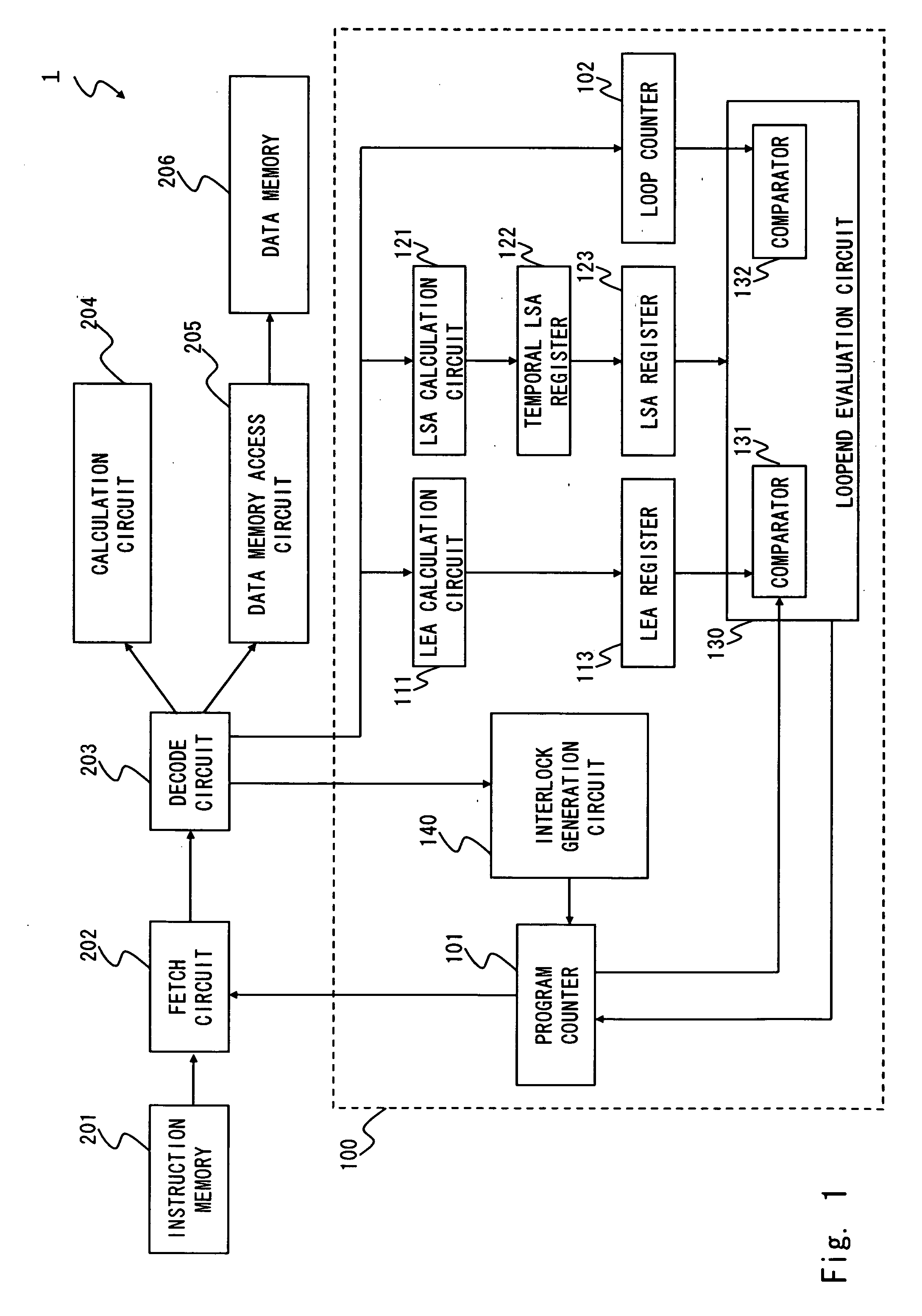
[0059]A configuration of the processor of this embodiment is described hereinafter in detail with reference to FIG. 1. The processor 1 is for example a processor to process an instruction in a pipeline and is a DSP capable of executing a loop instruction. As shown in FIG. 1, the processor 1 includes an instruction memory 201, a fetch circuit 202, a decode circuit 203, a calculation circuit 204, a data memory access circuit 205, a data memory 206, and a loop control circuit 100. The loop control circuit 100 includes a program counter 101, a LEA calculation circuit 111, a LEA register 113, a LSA calculation...

second embodiment

[0095]A processor according to a second embodiment of the present invention is described hereinafter in detail. The processor of this embodiment interlocks only when the loop end instruction is executed before completing to execute the loop instruction so as to abort the execution of the loop end instruction and to execute the loop end instruction after executing the loop instruction.

[0096]A configuration of the processor of this embodiment is described hereinafter in detail with reference to FIG. 4. In FIG. 4, components identical to those in FIG. 1 are identical to those therein. As shown in FIG. 4, a processor 1 further includes a temporary LEA register 112 in the loop control circuit 100 in addition to the configuration of FIG. 1.

[0097]In this embodiment, the LEA calculation circuit 121 calculates LSA before the execution phase of the loop instruction, specifically in a phase following the decode phase (i.e. AC phase) of the loop instruction. The calculation of LEA is not limite...


PUM


Abstract

A loop control circuit of the present invention includes a program counter for sequentially indicating an address of an instruction, a LSA calculation circuit for calculating a loop start address of a loop start instruction, a LEA calculation circuit for calculating a loop end address of a loop end instruction, an interlock generation circuit for generating an interlock until a pipeline of a loop instruction is completed so as to suspend a pipeline process of the loop end instruction, and a loop end evaluation circuit for setting the program counter to the loop start address according to a result of a comparison between the program counter and the loop end address after the pipeline process of the loop instruction is completed.

Description

BACKGROUND OF THE INVENTION[0001]1. Field of the Invention[0002]The present invention relates to a circuit and a method for loop control method, and particularly to a circuit and a method for loop control used by a processor for processing an instruction in a pipeline.[0003]2. Description of the Related Art[0004]A processor with pipeline processing mechanism that executes an instruction by pipeline is known among various processors. A pipeline is divided into a plurality of phases (stages) such as fetching, decoding, and execution of instructions. A plurality of the pipelines are overlapped to each other and the process of the next instruction is sequentially started before completing the process of the preceding instruction. Processes are intended to speed up by processing the plurality of instructions simultaneously in this way. A pipeline process is to process a series of phases from the fetch to execution phases for each instruction.[0005]FIGS. 10A and 10B are configuration exam...

Claims


Application Information

Patent Timeline
IPC IPC(8): G06F9/44
CPCG06F9/325G06F9/3867G06F9/381
Inventor CHIBA, SATOSHI
Owner RENESAS ELECTRONICS CORP
Learn More