
Input/output control apparatus, input/output control system, and input/output control method

a control apparatus and control system technology, applied in the field of input/output control apparatus, input/output control system, input/output control method, can solve the problems of limited hardware resources including input/output devices that have to be shared, hardly conceivable to use a configuration, and it is impossible to make a judgment on which device driver of the respective oss to be called

Inactive Publication Date: 2007-08-02
NTT DOCOMO INC
View PDF7 Cites 25 Cited by
  • Summary
  • Abstract
  • Description
  • Claims
  • Application Information

AI Technical Summary

Benefits of technology

[0071] The present invention has been made in view of the above points An object of the present invention is therefore to provide an input / output control apparatus, an input / output control system and an input / output control method, designed in consideration of efficiency, non-dependency of higher layer platforms, and usability.

Problems solved by technology

secondly, upon receipt of the interrupt signal, the CPU stops a process being performed at the time, and then calls a device driver corresponding to the interrupt number.
Under such an environment, limited hardware resources including input / output devices have to be shared by multiple OSs.
In this case, it is hardly conceivable to use a configuration in which each of the OSs independently includes a device driver of a network interface.
This is because it is impossible to previously make a judgment on which one of the device drivers of the respective OSs is to be called for a hardware interrupt which occurs when receiving data.
The VMM, however, cannot grasp which OS is being used by the user at an arbitrary time.
Accordingly, for example, in a case where an input of data from the keyboard causes an interrupt, the VMM cannot recognize which OS the interrupt is caused for.
It is, however, difficult to perform the same processing on data which is inputted from a keyboard.
Likewise, a problem occurs when data is outputted to the display device.
If all of the OSs individually hold the respective display drivers, and output data at their own choices, a conflict for the display device occurs, as a matter of course.
Moreover, even in a case where data to be outputted to a certain OS is aggregated, the correct output result cannot be displayed for the user without recognizing which OS is to output the data at the time.
There are, however, problems in such a solution by means of GUI servers.
The first problem is that contexts need to be switched between OSs very often since all of the GUI client applications of the respective OSs perform input and output processing separately.
Under the multiple OSs environment, it takes a long time to perform processes for saving and restoring contexts when the contexts are switched between the OSs.
In particular, context switching becomes a large bottleneck in output processing to a display device since a processing speed is important in the output processing.
Moreover, in an environment where a power saving processing is absolutely required as in the case of a mobile terminal, context switching also becomes a large factor causing an increase of electricity consumption.
The second problem is that the solution largely depends on platforms or applications of each of the OSs.
The third problem is a security risk associated with the fact that all of the inputs and outputs processing are handled by the GUI servers.
Since a GUI server is an “unprivileged process (user authorization)”, its tamper resistance is weak in comparison with an OS which is a “privileged process (kernel authorization)”.
In a case where the GUI server is tampered with, the input and output of the OS may be inappropriately processed.
This may causes an event in which an input result is passed to a wrong input destination, or in which an output result of the OS which is not supposed to be displayed is displayed.

Method used


Image

  • Input/output control apparatus, input/output control system, and input/output control method
  • Input/output control apparatus, input/output control system, and input/output control method
  • Input/output control apparatus, input/output control system, and input/output control method

Examples


first embodiment

(Input / Output Control System)

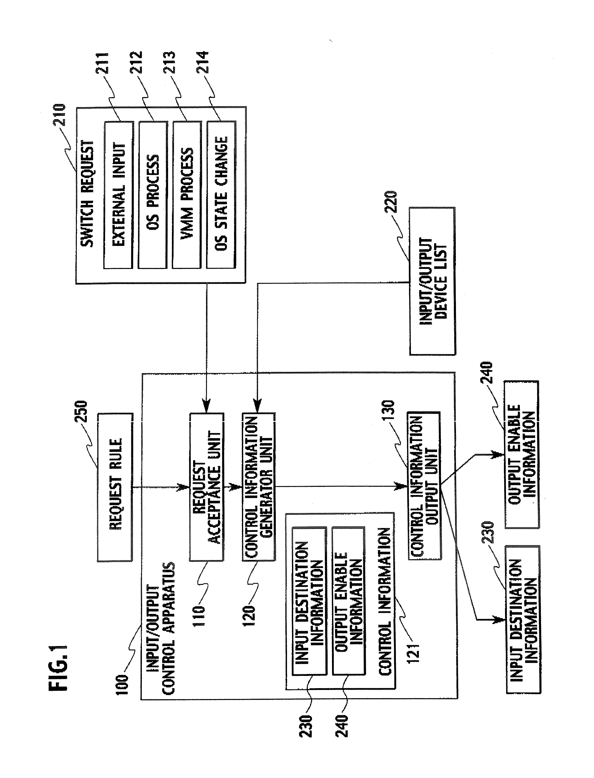
[0110]FIG. 1 shows a system configuration of an input / output control apparatus according to a first embodiment of the present invention.

[0111] For example, in a case where multiple OSs operate on a VMM, and a specific OS among the multiple OSs occupies and uses a specific device at an arbitrary time, the input / output control apparatus 100 performs the processing of making a judgment on which OS occupies the specific device, of switching the OSs, or the like.

[0112] As the aforementioned specific device, HIDs typified by a keyboard as an input device, or a display device as an output device can be cited as typical examples.

[0113] For example, suppose that a user intends to use a program, which operates on another OS, and then presses a switching button previously provided to a computer.

[0114] The input / output control apparatus 100 detects that the switching button has been pressed, and then generates control information in order for the OS, on which ...

second embodiment

(Input / Output Control System)

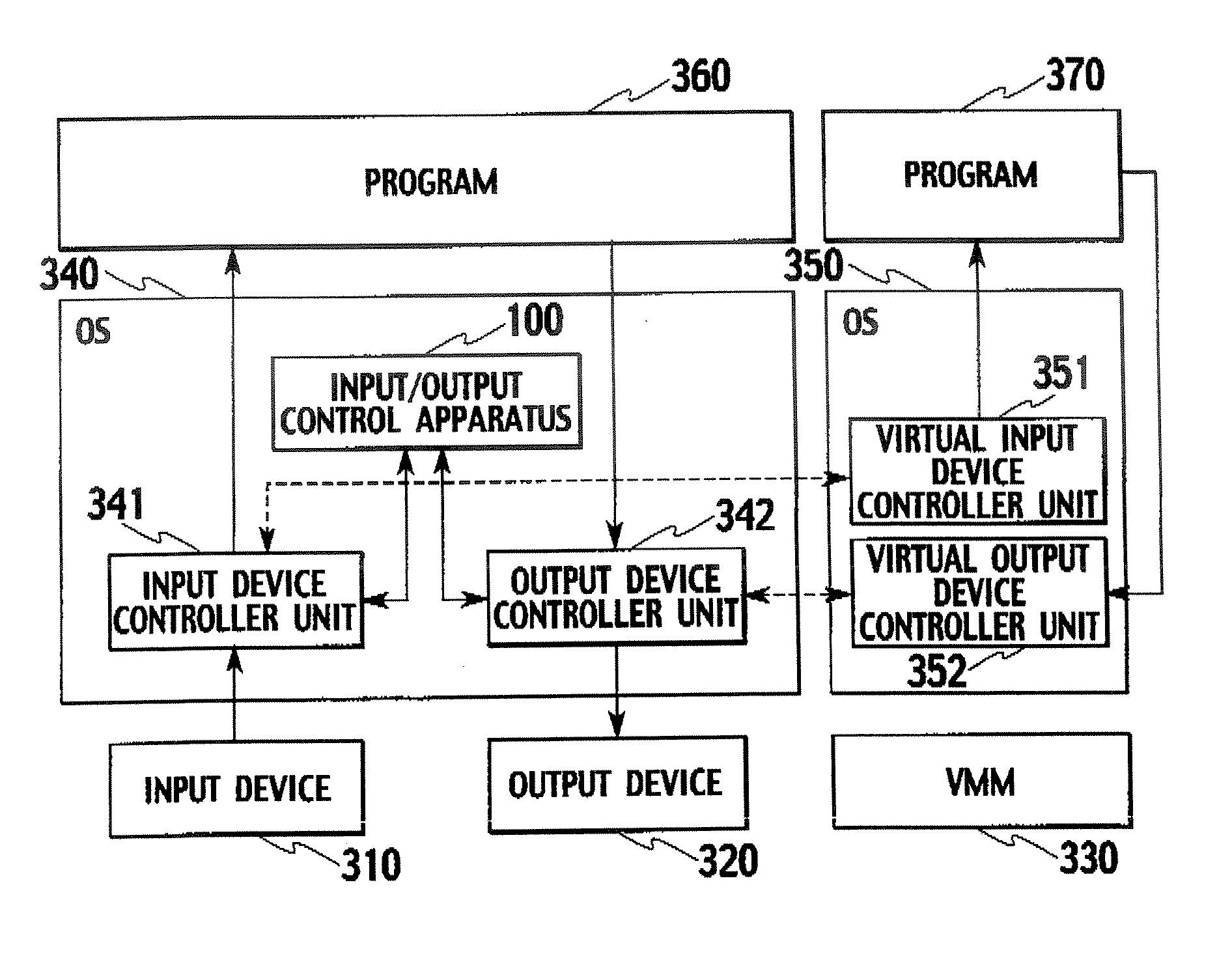
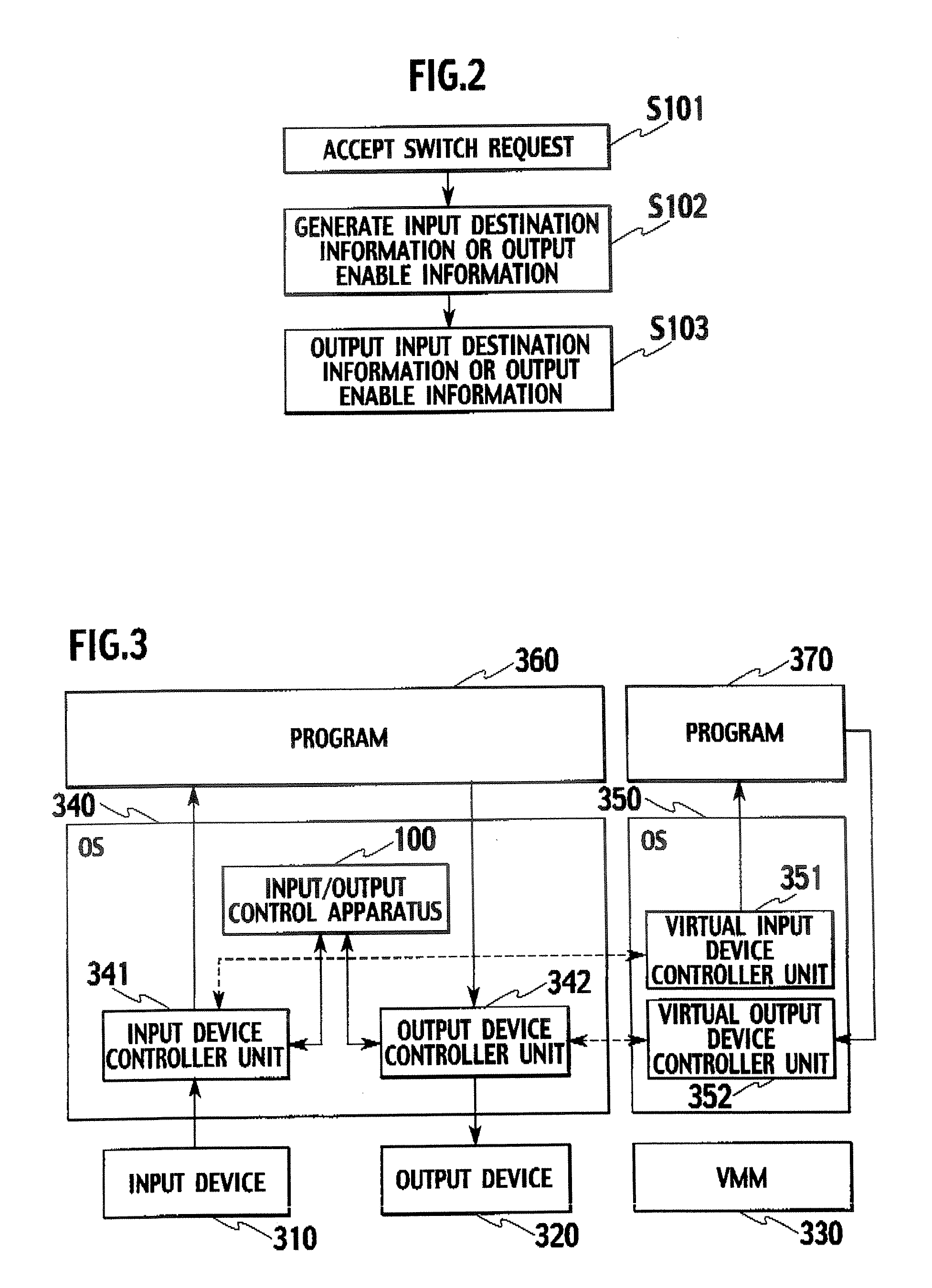
[0252]FIG. 3 shows a system configuration of a multiple OSs environment including an input / output control apparatus 100 according to a second embodiment.

[0253] An input / output control system according to the second embodiment is provided with an OS 340, an OS 350, a program 360, a program 370, an input device 310, an output device 320, and a VMM 330. The programs 360 and 370 operate on the OSs 340 and 350, respectively.

[0254] Moreover, the OS 340 is provided with the input / output control apparatus 100, an output device controller unit 342 capable of controlling the output device 320, and an input device controller unit 341 capable of controlling the input device 310.

[0255] Furthermore, the OS 350 is provided with a virtual input device controller unit 351, and a virtual output device controller unit 352.

[0256] Here, the OS 340 is assumed to be the secure OS, which is described in the first embodiment, and the OS 350 is assumed to be a general OS, f...

third embodiment

[0305] In a third embodiment, descriptions will be provided of a case where each OS is provided with the input device controller unit and the output device controller unit.

[0306] An input / output control system according to the third embodiment is provided with an OS 440, an OS 450, a program 460, a program 470, an input device 410, an output device 420, and a VMM 430, as shown in FIG, 5. The programs 460 and 470 operate on the OSs 440 and 450, respectively.

[0307] The OS 440 is provided with an input device controller unit 441, and an output device controller unit 442. The OS 450 is provided with an input device controller unit 451, and an output device controller unit 452.

[0308] Furthermore, the VMM 430 is provided with an input / output control apparatus 100.

[0309] In the third embodiment, each of the OSs, which are the OS 440 and OS 450, includes the input device controller unit 441 or 451, and the output device controller unit 442 or 452, which respectively control the input de...


PUM


Abstract

An input / output control apparatus includes: a request acceptance unit configured to accept a switch request for requesting to change an operating system occupying any one of the input device and the output device; a control information generator unit configured to generate control information including any one of input destination information and output enable information in response to the switch request; and a control information output unit configured to output any one of the input destination information and the output enable information. The input destination information includes at least information for specifying an input destination operating system to which information inputted from the input device is inputted; and the output enable information includes at least information for specifying whether or not each of the plurality of operating systems can output information to the output device.

Description

CROSS REFERENCE TO RELATED APPLICATION [0001] This application is based upon and claims the benefit of priority from the prior Japanese Patent Application No. P2006-9190, filed on Jan. 17, 2006; and the prior Japanese Patent Application No. P2006-341835, filed on Dec. 19, 2006; the entire contents of which are incorporated herein by reference BACKGROUND OF THE INVENTION [0002] 1. Field of the Invention [0003] The present invention relates to an input / output control apparatus, an input / output control system, and an input / output control method, which control shared use of input / output devices by more than one operating system (hereinafter referred to as “OS”). [0004] 2. Description of the Related Art [0005] In a computer on which a single OS operates, software for controlling input / output devices (hereinafter referred to as “device drivers”) allows the OS itself and a program operating on the OS to access the input / output devices provided to the computer, and the device driver is the ...

Claims


Application Information

Patent Timeline
IPC IPC(8): G06F9/44
CPCG06F9/45533G06F9/45558G06F2009/45579
Inventor FUJIMOTO, HIROSHISUZUKI, TAKASHIOHTA, KEN
Owner NTT DOCOMO INC
Learn More