Removable mountable aerodynamic bayonet antenna apparatus and method

a technology of aerodynamic bayonets and antennas, which is applied in the direction of wind-induced force reduction, collapsible antenna means, and quick-release antenna elements, etc., can solve the problems of related art antennas, at least in part, remaining exposed to hazards, fatigue, and flutter, so as to reduce fatigue, improve the effect of signal transmission, and reduce drag

Active Publication Date: 2007-08-02
TYCO ELECTRONICS LOGISTICS AG (CH)
View PDF64 Cites 7 Cited by
  • Summary
  • Abstract
  • Description
  • Claims
  • Application Information

AI Technical Summary

Benefits of technology

[0007] An advantage of the present invention is the protection of the antenna assembly, containing the delicate antenna circuitry, from corrosion, short-circuiting, fatigue, accidental damage, and vandalism. Other advantages include optimization of the signal transmission and the reduction of drag on, and the elimination of fatigue as well as flutter of, the antenna assembly. Further advantages include the enabling of rapid alignment of the antenna assembly during installation and an omni-directional radiation pattern which allows either edge of the apparatus to function as a leading edge without adversely affecting performance. Other features of the present invention are disclosed, or are apparent, in the section entitled “Modes for Carrying Out the Invention,” disclosed, infra.

Problems solved by technology

However, these related art antennas, at least in part, remain exposed to hazards, such as corrosion, accidental structural damage, vandalism, drag, fatigue, and flutter.

Method used


Image

  • Removable mountable aerodynamic bayonet antenna apparatus and method
  • Removable mountable aerodynamic bayonet antenna apparatus and method
  • Removable mountable aerodynamic bayonet antenna apparatus and method

Examples


Embodiment Construction

,” disclosed, infra.

BRIEF DESCRIPTION OF THE DRAWINGS

[0008] For better understanding of the present invention, reference is made to the below-referenced accompanying Drawings. Reference numbers refer to the same or equivalent parts of the present invention throughout the several figures of the Drawings.

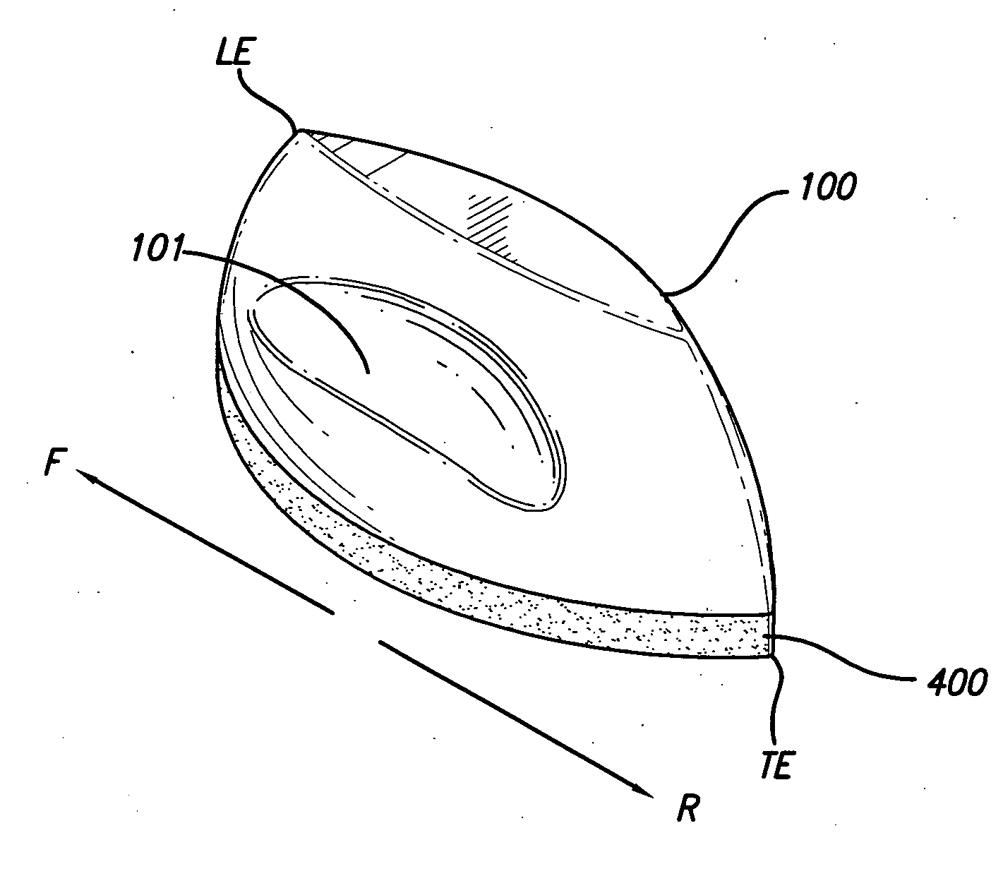
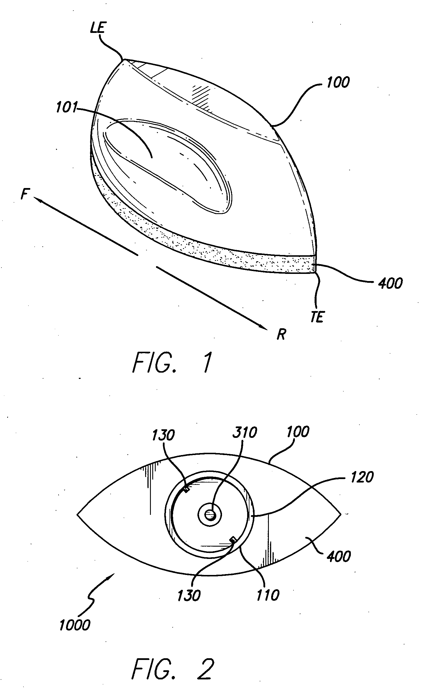
[0009]FIG. 1 is a perspective view of a mountable antenna apparatus, in accordance with the present invention.

[0010]FIG. 2 is a bottom view of mountable antenna apparatus, in accordance with the present invention.

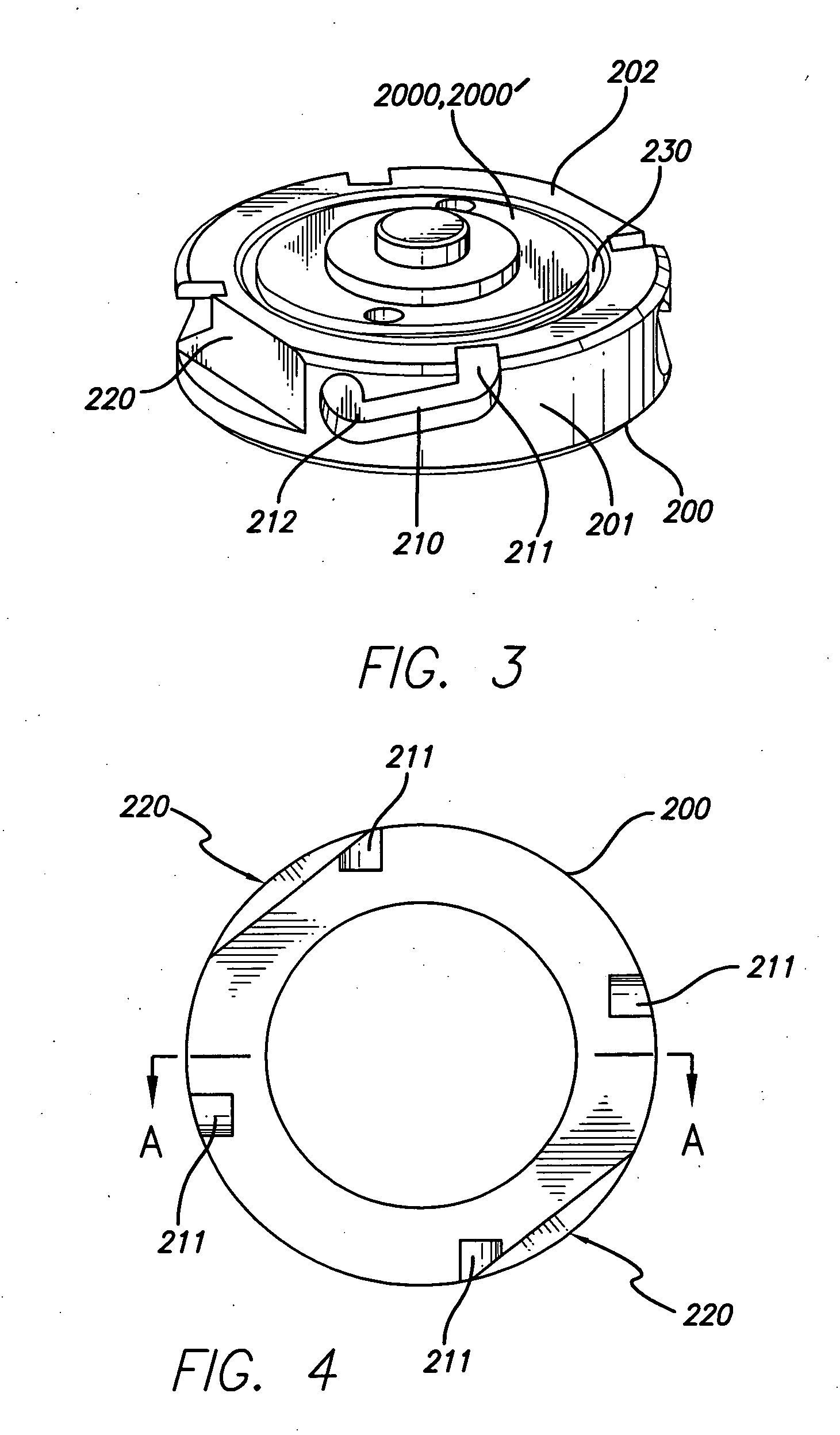
[0011]FIG. 3 is a perspective view of a bayonet adapter threaded on an NMO mount, whereby a retrofitted NMO mount is effected, in accordance with the present invention.

[0012]FIG. 4 is a top view of the bayonet adapter, showing the orientation of two setbacks and the locations of four ramped recesses having insertion notches therein formed in relation to a cross section A-A, by example only and in accordance with the present invention.

[0013]FIG. 5 is a cross-sectional vi...


PUM


Abstract

A mountable antenna apparatus and method involving a housing member (100); a bayonet adapter (200); and an antenna assembly (300) being disposed within the housing member (100). The housing member (100) comprises an aerodynamic configuration for reducing drag on, and for eliminating fatigue as well as flutter of, the antenna assembly (300); and the aerodynamic configuration comprises a feature such as an ogive, an ogivoid, a semi-ogivoid, a hemi-ogivid, and a quasi-ogivoid.

Description

TECHNICAL FIELD [0001] The present invention relates to antenna apparatuses and methods. More particularly, the present invention relates to antenna apparatuses and methods for vehicles. Even more particularly, the present invention relates to removable mountable antenna apparatuses and methods for vehicles. BACKGROUND ART [0002] A common current vehicle antenna in the related art is an antenna rod which is fastened to a base using a quick-connect coupling assembly; and the second quick-connect coupling assembly connects an antenna cable with a terminal on a radio. Another antenna apparatus is mounted onto a vehicle by a base and a fastener, wherein the base is removably attached to the vehicle, the base including a mounting portion and a housing component. The mounting portion has a main body with an arm therefrom extending, a top portion, and an engaging element for removably attaching the base assembly to the vehicle. The housing is coupled to the base; and the fastener has a gui...

Claims


Application Information

Patent Timeline
Patent Type & Authority Applications(United States)
IPC IPC(8): H01Q1/12
CPCH01Q1/005H01Q1/3275H01Q1/088
Inventor CISLO, DONALD M.
Owner TYCO ELECTRONICS LOGISTICS AG (CH)
Why Eureka
Try Eureka