Mountable and adjustable aerodynamic antenna apparatus and method

an antenna and aerodynamic technology, applied in the direction of antennas, antenna details, antenna adaptation in movable bodies, etc., can solve the problems of affecting the signal transmission and affecting the signal transmission efficiency of related art antennas. , to achieve the effect of reducing drag, eliminating fatigue, and optimizing signal transmission

Active Publication Date: 2007-10-04
TYCO ELECTRONICS LOGISTICS AG (CH)
View PDF11 Cites 1 Cited by
  • Summary
  • Abstract
  • Description
  • Claims
  • Application Information

AI Technical Summary

Benefits of technology

[0007] An advantage of the present invention is the protection of the antenna assembly, containing the delicate antenna circuitry, from corrosion, short-circuiting, fatigue, accidental damage, and vandalism. Other advantages include optimization of the signal transmission and the reduction of drag on, and the elimination of fatigue as well as flutter of, the antenna assembly. Further advantages include the enabling of rapid adjustment of the antenna assembly by the user and an omni-directional radiation pattern which allows any orientation of the antenna assembly without adversely affecting performance. Other features of the present invention are disclosed, or are apparent, in the section entitled “Modes for Carrying out the Invention,” disclosed, infra.

Problems solved by technology

However, these related art antennas remain exposed to hazards, such as corrosion, accidental structural damage, vandalism, drag, fatigue, and flutter.

Method used


Image

  • Mountable and adjustable aerodynamic antenna apparatus and method
  • Mountable and adjustable aerodynamic antenna apparatus and method
  • Mountable and adjustable aerodynamic antenna apparatus and method

Examples


Embodiment Construction

,” disclosed, infra.

BRIEF DESCRIPTION OF THE DRAWINGS

[0008] For a better understanding of the present invention, reference is made to the below-referenced accompanying Drawings. Reference numbers refer to the same or equivalent parts of the present invention throughout the several figures of the Drawings.

[0009]FIG. 1 is an exploded perspective view of a mountable and adjustable antenna apparatus, in accordance with the present invention.

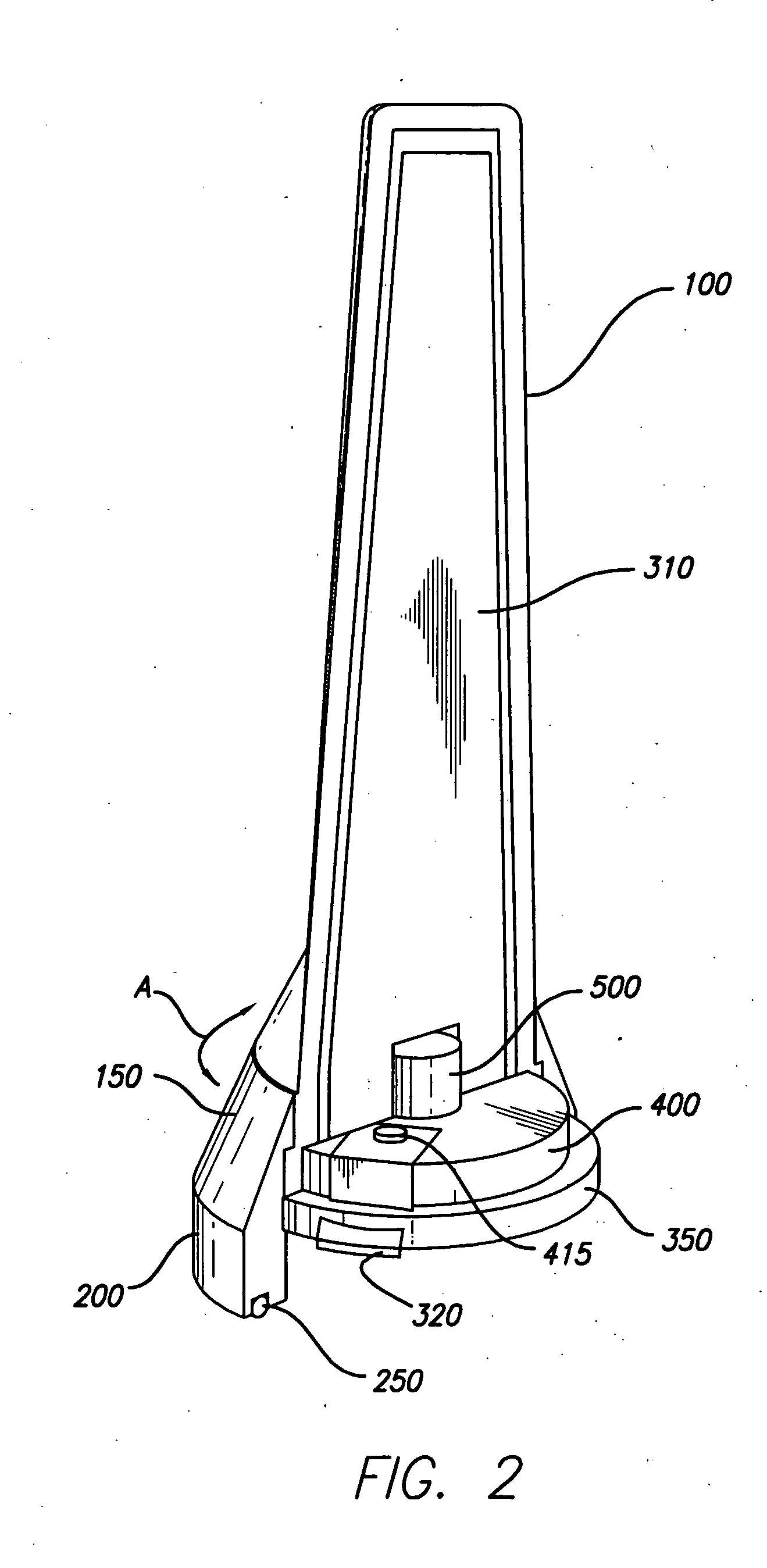
[0010]FIG. 2 is a cut-away perspective view of mountable and adjustable antenna apparatus, in accordance with the present invention.

MODES FOR CARRYING OUT THE INVENTION

[0011]FIG. 1 illustrates, in an exploded perspective view, a mountable and adjustable antenna apparatus 1000, in accordance with the present invention. The mountable and adjustable antenna apparatus 1000 comprises a top housing member 100, a bottom housing member 200, and an antenna assembly 300 being disposed within the top housing member 100. The top housing member 100 is in a ro...


PUM


Abstract

A mountable and adjustable antenna apparatus (1000) and a method (M) involving a top housing member (100), a bottom housing member (200), and an antenna assembly (300) being disposed within the top housing member (100), the top housing member (100) being in rotatable relation to the bottom housing member (200), and the antenna assembly (300) being in fixed relation to the top housing member (100). The top housing member (100) has an aerodynamic configuration for reducing drag on, and for eliminating fatigue as well as flutter of, the antenna assembly (300).

Description

TECHNICAL FIELD [0001] The present invention relates to antenna apparatuses and methods. More particularly, the present invention relates to antenna apparatuses and methods for vehicles. Even more particularly, the present invention relates to mountable and adjustable antenna apparatuses and methods for vehicles. BACKGROUND ART [0002] A common current vehicle antenna in the related art is an antenna rod which is fastened to a base in a ball and socket configuration, i.e., the ball is disposed at the proximal end of the antenna for universal pivoting on the socket which is mounted to the base. One such apparatus comprises a socket having a plurality of slots within which the antenna may be radially disposed by user-selection. Another apparatus is window-mountable and comprises an outer cover being disposed at the base of the antenna and having a cross section being elongated in the direction of the vehicle's travel, the cover including an enlarged section covering a loading coil for ...

Claims


Application Information

Patent Timeline
Patent Type & Authority Applications(United States)
IPC IPC(8): H01Q1/32
CPCH01Q1/1207H01Q1/282H01Q9/40H01Q9/30H01Q1/42
Inventor CISLO, DONALD M.
Owner TYCO ELECTRONICS LOGISTICS AG (CH)
Why Eureka
Try Eureka