
Variable compression ratio device of internal combustion engine

Inactive Publication Date: 2007-08-02
HONDA MOTOR CO LTD
View PDF5 Cites 7 Cited by
  • Summary
  • Abstract
  • Description
  • Claims
  • Application Information

AI Technical Summary

Benefits of technology

[0008] The present invention has been achieved in view of the above circumstances. An object of an embodiment of the present invention is to provide a variable compression ratio device of an internal combustion engine capable of performing smooth switching of the position between a low compression ratio position and a high compression ratio position by an inertia force of a piston outer part, and reducing the weight of a piston while making use of the original advantage.

Problems solved by technology

However, since a skirt part which is slidably fitted to an inner peripheral surface of a cylinder bore to stabilize the posture of the piston is formed at the piston outer part, when the piston outer part switches the position between the low compression ratio position and the high compression ratio position by using its inertia force, the piston outer part is slid accompanying the skirt part on the inner peripheral surface of the cylinder bore, so that a delay in switching of the position sometimes occurs due to sliding resistance of the skirt part.
In addition, since the piston inner part is slidably fitted to the inner peripheral surface of the piston outer part over its entire outer peripheral surface, the fitting area of the piston inner part and the piston outer part is large, thereby increasing the weight of the piston.

Method used


Image

  • Variable compression ratio device of internal combustion engine
  • Variable compression ratio device of internal combustion engine
  • Variable compression ratio device of internal combustion engine

Examples


first embodiment

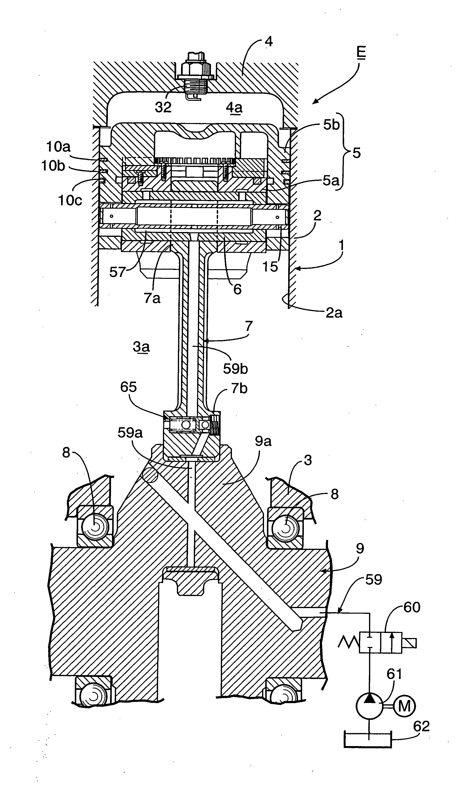
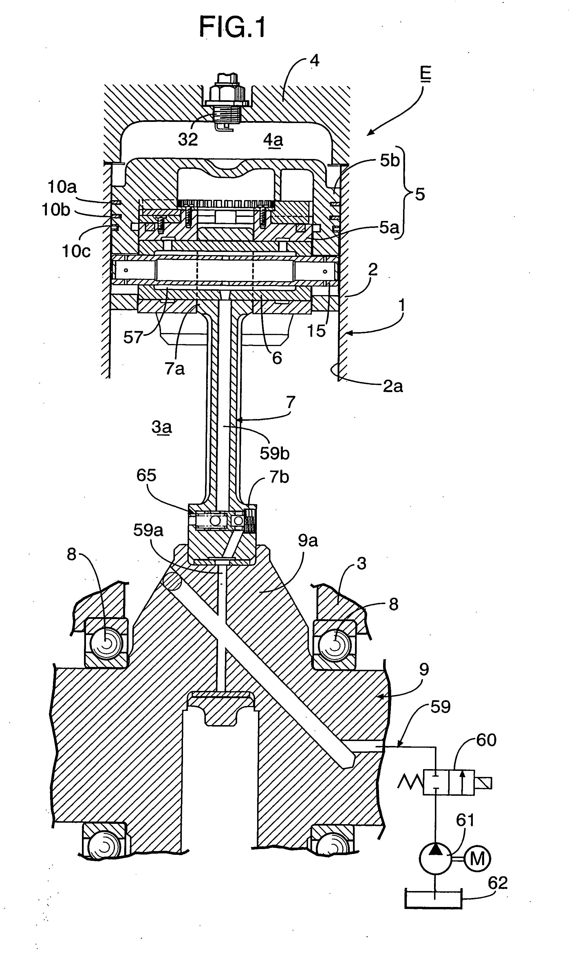
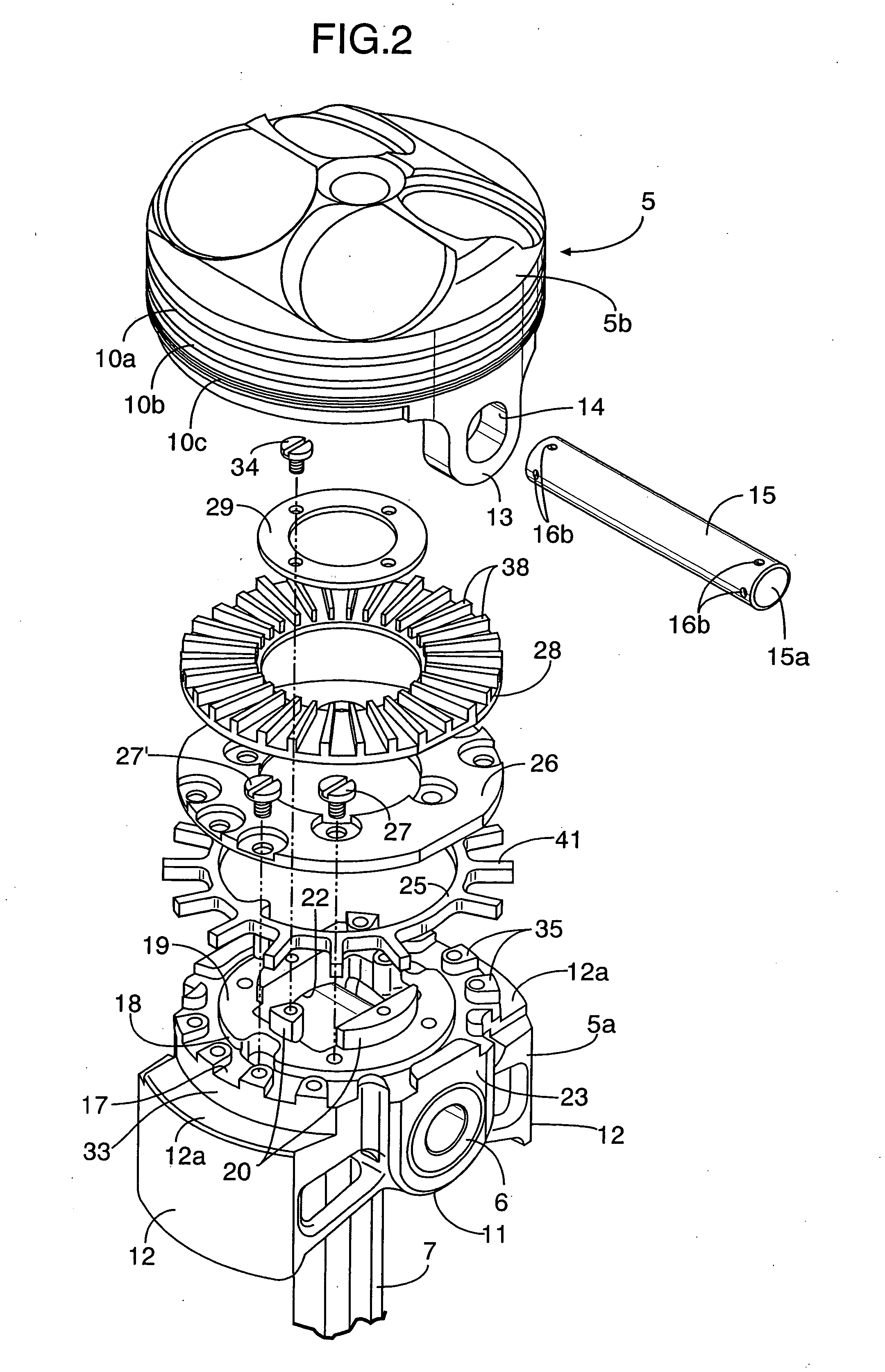
[0044] the present invention will be described with reference to FIGS. 1 to 18. In FIGS. 1 and 5, an engine body 1 of an internal combustion engine E includes a cylinder block 2 having a cylinder bore 2a, a crankcase 3 which is connected to a lower end of the cylinder block 2 and a cylinder head 4 which has a pent roof type combustion chamber 4a connected to an upper end of the cylinder bore 2a and which is connected to an upper end of the cylinder block 2. Threadedly fitted to the cylinder head 4 are an intake valve 31i and an exhaust valve 31e that open and close an intake port 30i and an exhaust port 30e which are opened in a ceiling surface of the combustion chamber 4a, and an ignition plug 32 with electrodes facing a central portion of the combustion chamber 4a.

[0045] A small end portion 7a of a connecting rod 7 is connected via a piston pin 6 to a piston 5 which is slidably fitted in the cylinder bore 2a. A large end portion 7b of the connecting rod 7 is connected via a pair o...


PUM


Abstract

A variable compression ratio device of an internal combustion engine includes a piston inner part connected to a connecting rod and a piston outer part fitted on an outer periphery of the piston inner part. The piston outer part is only slidably in an axial direction, and is movable between a low compression ratio position near the piston inner part and a high compression ratio position near the combustion chamber. A skirt part is slidable and is guided by an inner peripheral surface of a cylinder bore of an engine. The skirt part is integrally formed on the piston inner part. A peripheral wall of the piston outer part is terminated directly above the skirt part. Thus, switching of the position between the low compression ratio position and the high compression ratio position by an inertia force of the piston outer part is performed smoothly with a reduction in weight of the piston.

Description

CROSS-REFERENCE TO RELATED APPLICATION [0001] The present application claims priority under 35 USC 119 to Japanese Patent Application No. 2005-379083 filed on Dec. 28, 2005 the entire contents of which are hereby incorporated by reference. BACKGROUND OF THE INVENTION [0002] 1. Field of the Invention [0003] The present invention relates to an improvement of a variable compression ratio device of an internal combustion engine, wherein a piston includes a piston inner part which is connected to a connecting rod via a piston pin and a piston outer part which is fitted on an outer periphery of the piston inner part so as to be only slidable in an axial direction. The piston outer part is movable between a low compression ratio position near the piston inner part and a high compression ratio position near a combustion chamber, with an outer end surface of the piston outer part facing the combustion chamber. A cam mechanism is provided between the piston inner part and the piston outer par...

Claims


Application Information

Patent Timeline
IPC IPC(8): F02B75/04F02D15/02
CPCF02D15/02F02B75/044
Inventor ISHIKAWA, SEIICHIROKONDO, TAKASHIYOSHIDA, KAZUO
Owner HONDA MOTOR CO LTD
Learn More