
Method of manufacutring slider

a slider and slider technology, applied in the direction of manufacturing tools, maintaining head carrier alignment, instruments, etc., can solve the problems of large use limitation, manufacturing method cannot manufacture e.g. tunnel magneto-resistive (tmr) wafers, and difficult to eliminate or weaken side surface stress, so as to reduce the height of the edge jump on the slider and avoid the effect of edge jump

Inactive Publication Date: 2007-08-02
SAE MAGNETICS (HK) LTD
View PDF4 Cites 1 Cited by
  • Summary
  • Abstract
  • Description
  • Claims
  • Application Information

AI Technical Summary

Benefits of technology

[0011]One aspect of the present invention is to provide a slider manufacturing method which can provide a pre-stress on the ABS of the row bar, the pre-stress can counterbalance or weaken cutting stress generated in cutting process so as to avoid producing edge jumps on the slider or reduce a height of the edge jump on the slider.

Problems solved by technology

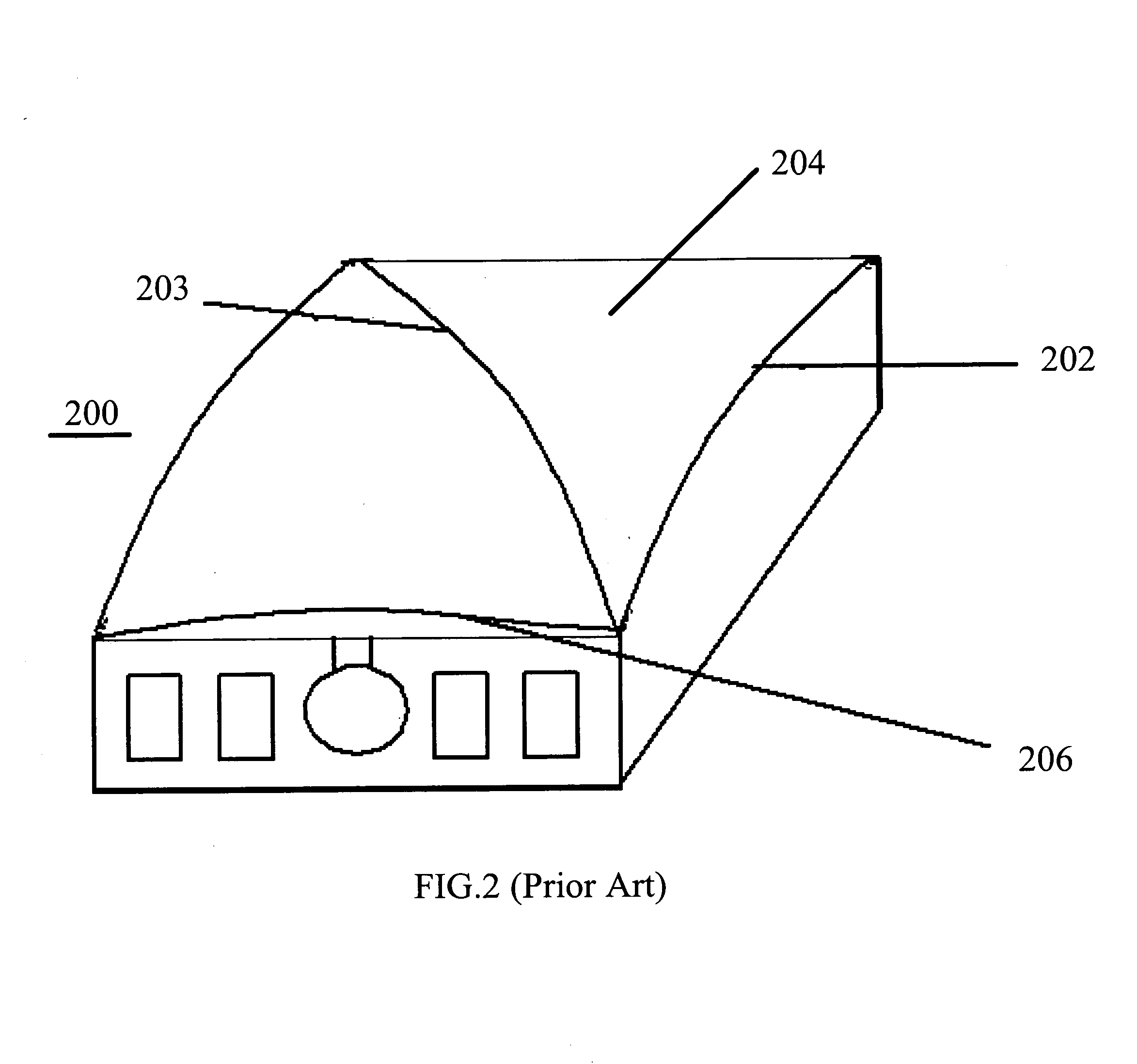
However, during the cutting process, it is prone to produce side surface stress (cutting stress) on fracture face of the slider 400, and the side surface stress is difficult to eliminate or weaken during the cutting process or after the cutting process.
As a result, the manufacturing method cannot manufacture e.g. tunnel magneto-resistive (TMR) wafers, i.e., the method has a great limitation in use.
However, side surface stress is still produced on fracture face of the slider 400, and difficult to eliminate or weaken during the cutting process or after the cutting process.

Method used


Image

  • Method of manufacutring slider
  • Method of manufacutring slider
  • Method of manufacutring slider

Examples


Embodiment Construction

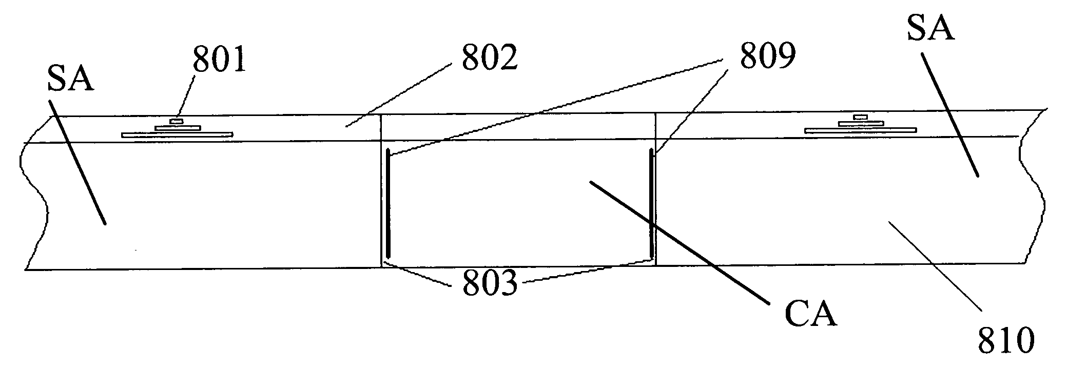
[0030]Various preferred embodiments of the instant invention will now be described in conjunction with the drawings. As illustrated above, the invention provides a slider manufacturing method to form a stress absorption region adjacent to slider cut line in a cutting region defined by two adjacent slider cutting lines. When the row bar is cut by a cutter, such as a diamond cutting wheel, into a plurality of individual sliders along the slider cutting lines, the cutting stress generated in cutting process is partly or fully absorbed by the stress absorption region, thus avoiding forming clear edge jumps at the edges of the ABS of the slider after cutting process, and then a risk that the slider to scratch the disk surface can be eliminated. More specifically, the slider manufacturing method of the invention forms at least one point scribe line of a certain depth at the cutting region adjacent to the cutting lines of the row bar in advance using a scribing tool, e.g. laser scriber, be...


PUM

PropertyMeasurementUnit
depthaaaaaaaaaa
depthaaaaaaaaaa
distanceaaaaaaaaaa

Abstract

A slider manufacturing method of the invention comprises: providing a row bar constructed by a plurality of slider bodies which has a surface for forming air bearing surface; forming a plurality of cutting lines on the surface for forming air bearing surface of the row bar; forming a stress absorption region adjacent to the cut line in a cutting region defined by two adjacent cutting lines; grinding the surface for forming air bearing surface of the row bar; and cutting the row bar along the cutting lines to form a plurality of individual sliders. When the row bar is cut by a cutter into a plurality of individual sliders along the cutting lines, stress generated in the cutting region adjacent to cutting lines during cutting process is partly or fully absorbed by the stress absorption region, thus no clear edge jumps will form at the edges of the ABS of the slider after cutting process, and the risks of disk surface scratching by slider also being eliminated.

Description

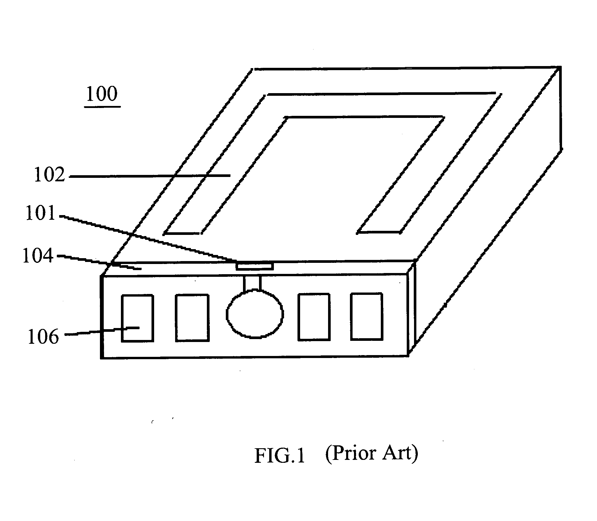
FIELD OF THE INVENTION[0001]The present invention relates to a method for manufacturing disk drive units, and more particularly to a method of manufacturing slider used in disk drive unit that can effectively improve slider's profile.BACKGROUND OF THE INVENTION[0002]Disk drive unit is a kind of information storage device used widely in the world. The disk drive unit has a very small slider incorporating a read / write transducer therein. The slider is flying above a rotary magnetic medium such as a disk, and moves selectively from track to track of the disk surface to read data from or write data to the disk.[0003]FIG. 1 shows an ideal slider. The slider 100 comprises a planar air bearing surface (ABS) 102. An alumina layer 104 formed at a front side of the slider 100, and a pole 101 is formed at a top portion of the alumina layer 104 to perform data reading / writing operation. A plurality of connecting pads 106 are formed on the alumina layer 104 for electrically connecting the slider...

Claims


Application Information

Patent Timeline
Patent Type & Authority Applications(United States)
IPC IPC(8): G11B5/127B23P17/00
CPCG11B5/1272G11B5/3173Y10T29/49048Y10T29/49798Y10T29/49052Y10T29/49041
Inventor TAN, ZHIHUAWANG, QUANBAOMA, YANZENG
Owner SAE MAGNETICS (HK) LTD
Learn More