Article made of biodegradable resin and method of making the same
- Summary
- Abstract
- Description
- Claims
- Application Information
AI Technical Summary
Benefits of technology
Problems solved by technology
Method used
Image

Examples
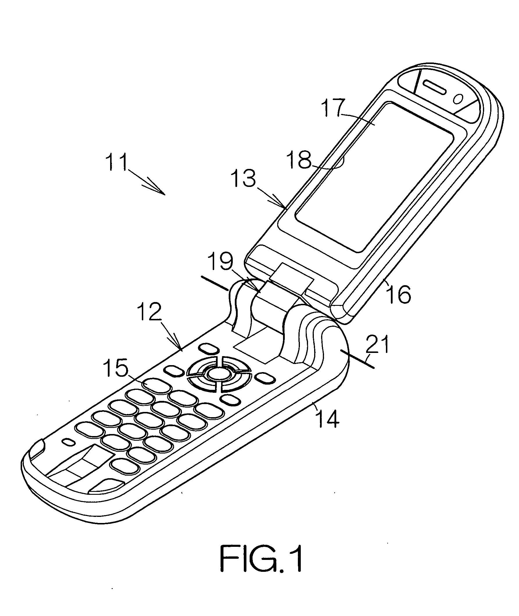
first embodiment
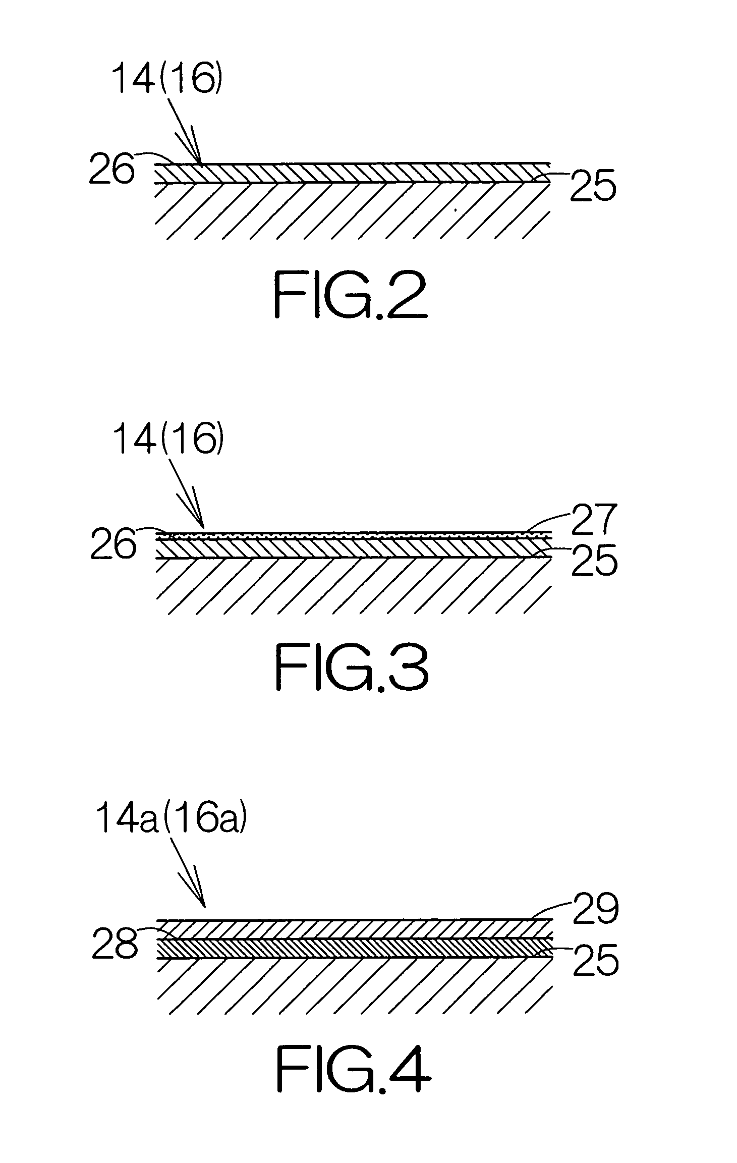
[0031]FIG. 2 schematically illustrates the cross-section of the main enclosure 14 according to the present invention. The main enclosure 14 includes a base or body 25. The base 25 is made of a biodegradable resin. Polylactic acid, cellulose acetate, cellulose polyacetate, or the like, may be utilized as the biodegradable resin. The thickness of the base 25 may be set at 1 mm approximately, for example.
[0032] The main enclosure 14 includes a coating film 26 made of resin. The coating film 26 covers over the surface of the base 25. The coating film 26 is formed based on solidification of a fluid coating material. A petroleum resin such as acrylic, epoxy, or the like, may be utilized as the resin. Here, the coating film 26 may be formed only on the inside surface of the base 25. The thickness of the coating film 26 may be set in a range from 1 μm to 20 μm approximately, for example.
[0033] The coating film 26 contains an electrically conductive material. The content of the electrically...
second embodiment
[0048]FIG. 4 schematically illustrates the cross-section of a main enclosure 14a according to the present invention. The main enclosure 14a includes an adhesive film 28 made of resin. The adhesive film 28 covers over the inside surface of the base 25. The thickness of the adhesive film 28 may be set in a range from 1 μm to 20 μm approximately, for example. The adhesive film 28 is formed based on solidification of a fluid adhesive. An insulative resin adhesive such as acrylic, epoxy, urethane, silane, fluorine, or the like, is utilized as the adhesive.
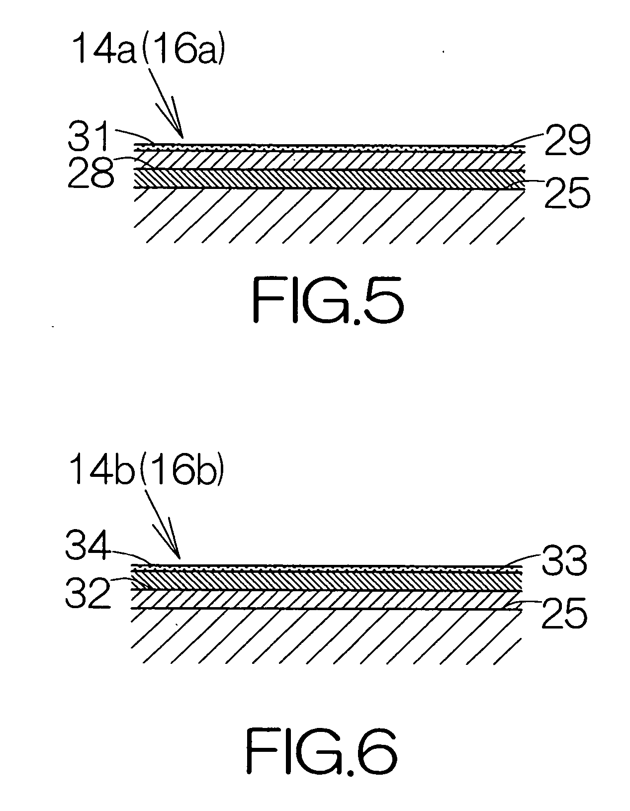
[0049] The surface of the adhesive film 28 is covered with a coating film 29. The coating film 29 is formed based on solidification of a fluid coating material. The thickness of the coating film 29 may be set in a range from 1 μm to 20 μm approximately, for example. The coating film 29 may contain an electrically conductive material or materials identical to those of the aforementioned coating film 26. The content of the electrically co...
third embodiment
[0059]FIG. 6 schematically illustrates the cross-section of a main enclosure 14b according to the present invention. The main enclosure 14b includes a coating film 32 made of resin. The coating film 32 covers over the inside surface of the base 25. A petroleum resin may be utilized as the resin, for example. The coating film 32 is formed based on solidification of a fluid coating material. The thickness of the coating film 32 may be set in a range from 1 μm to 20 μm approximately, for example. The coating film 32 contains an electrically conductive material or materials identical to those of the aforementioned coating films 26, 29.
[0060] An adhesive film 33 covers over the surface of the coating film 32. The thickness of the adhesive film 33 may be set in the range from 1 μm to 20 μm approximately, for example. The adhesive film 33 is formed based on solidification of a fluid adhesive. The type of adhesive may be identical to the type of adhesive which is utilized for the aforementi...
PUM
| Property | Measurement | Unit |
|---|---|---|
| Electrical conductivity | aaaaa | aaaaa |
| Electrical conductor | aaaaa | aaaaa |
| Adhesivity | aaaaa | aaaaa |
Abstract
Description
Claims
Application Information
 - R&D
- Intellectual Property
- Life Sciences
- Materials
- Tech Scout
- Unparalleled Data Quality
- Higher Quality Content
- 60% Fewer Hallucinations
Browse by: Latest US Patents, China's latest patents, Technical Efficacy Thesaurus, Application Domain, Technology Topic, Popular Technical Reports.
© 2025 PatSnap. All rights reserved.Legal|Privacy policy|Modern Slavery Act Transparency Statement|Sitemap|About US| Contact US: help@patsnap.com