
Solid-state, color-balanced backlight with wide illumination range

a color-balanced backlight and solid-state technology, applied in the field of backlights, can solve the problems of inability to adjust the color, damage the glass tube, and the need for a high-voltage power supply, and achieve the effect of preventing color measurement interferen

Active Publication Date: 2007-07-26
ASTRONAUTICS CORPORATION OF AMERICA
View PDF21 Cites 66 Cited by
  • Summary
  • Abstract
  • Description
  • Claims
  • Application Information

AI Technical Summary

Benefits of technology

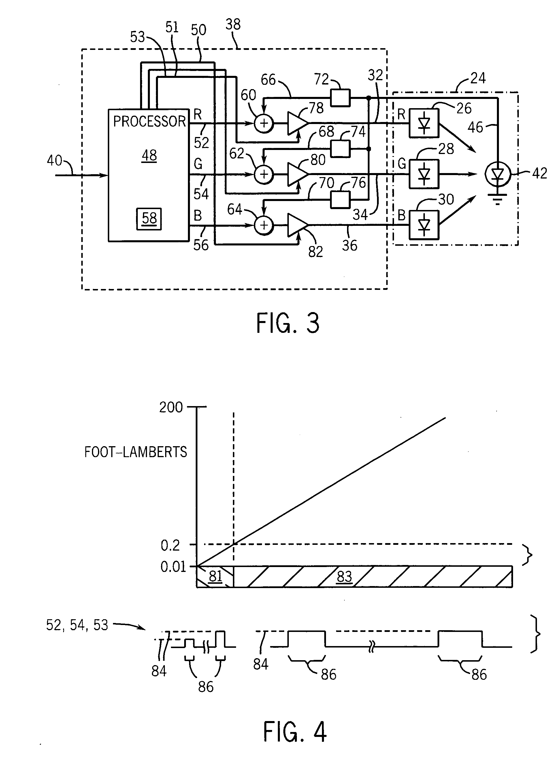
[0009] This brief measurement modulation period eliminates the need for color filters on multiple photodetectors that may age or degrade, or the need to balance the signals from multiple photodetectors, or correct for variations in those signals caused by age and temperature of different photodetectors. The feedback control of the LEDs may be combined with open loop pulse width modulation of the LEDs to permit an extremely wide range of illumination while retaining precise color balance enforced by the much narrower range of feedback color control. A narrower range of feedback allows use of a photodetector that has a narrower range but greater precision.
[0011] Thus it is an object of at least one embodiment of the invention to provide for measurement of the light from each color group without the need for isolating filters or multiple photodetectors associated with each color. By using modulation of the light sources to isolate the colors, a single photodetector may be used simplifying the design and preventing the need to calibrate or compensate among multiple detectors and further eliminating the cost and expense of filters and their possible degradation with time and temperature.
[0015] Thus it is an object of at least one embodiment of the invention to provide for an extremely simple measurement of the light output of each lamp group.
[0019] Thus it is an object of at least one embodiment of the invention to minimize the length of the second period by short modulation pulses while eliminating artifacts measurement signal rise and fall times.
[0025] Thus it is an object of at least one embodiment of the invention to separate the time of measurement of color balance from the time of illumination to prevent interference in the color measurement from changes in the total brightness of the backlight.

Problems solved by technology

In low light situations, too much illumination can interfere with dark adaptation and night vision goggles or similar equipment.
Fluorescent tubes have a number of disadvantages in avionics applications including: the need for a high voltage power supply, a fragility of the glass tube, a tendency to fail unexpectedly, low efficiency at low ambient temperatures, and a limited ability to change brightness level.
Maintaining this color balance as the backlight is varied in brightness, can be difficult because of different and often non-linear relationships between light output and current for each of the different colors of LEDs.
That is, over a given range, a uniform change in current provided to the LEDs for each color will tend to cause a color shifting of the backlight.

Method used


Image

  • Solid-state, color-balanced backlight with wide illumination range
  • Solid-state, color-balanced backlight with wide illumination range
  • Solid-state, color-balanced backlight with wide illumination range

Examples


Embodiment Construction

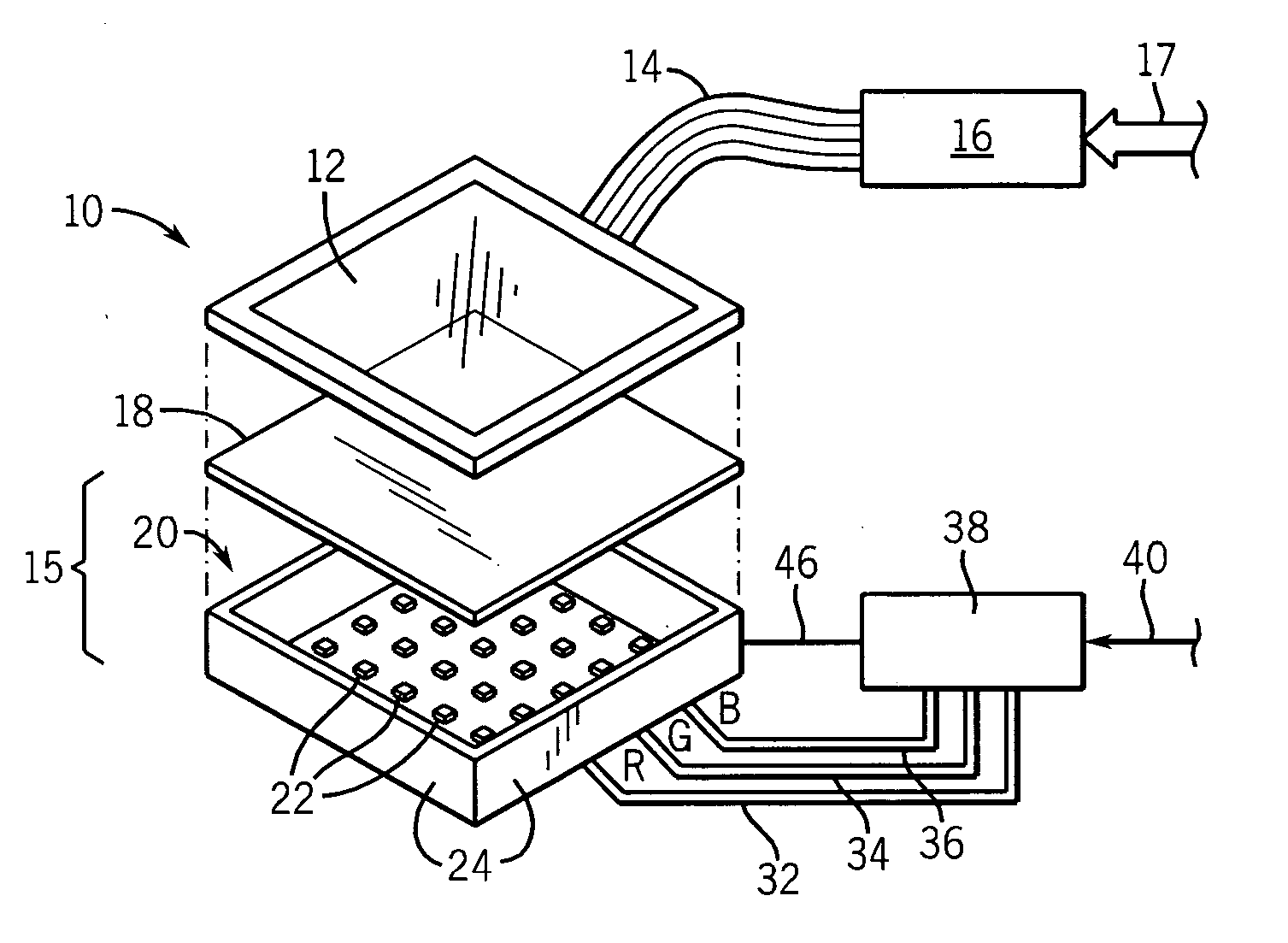
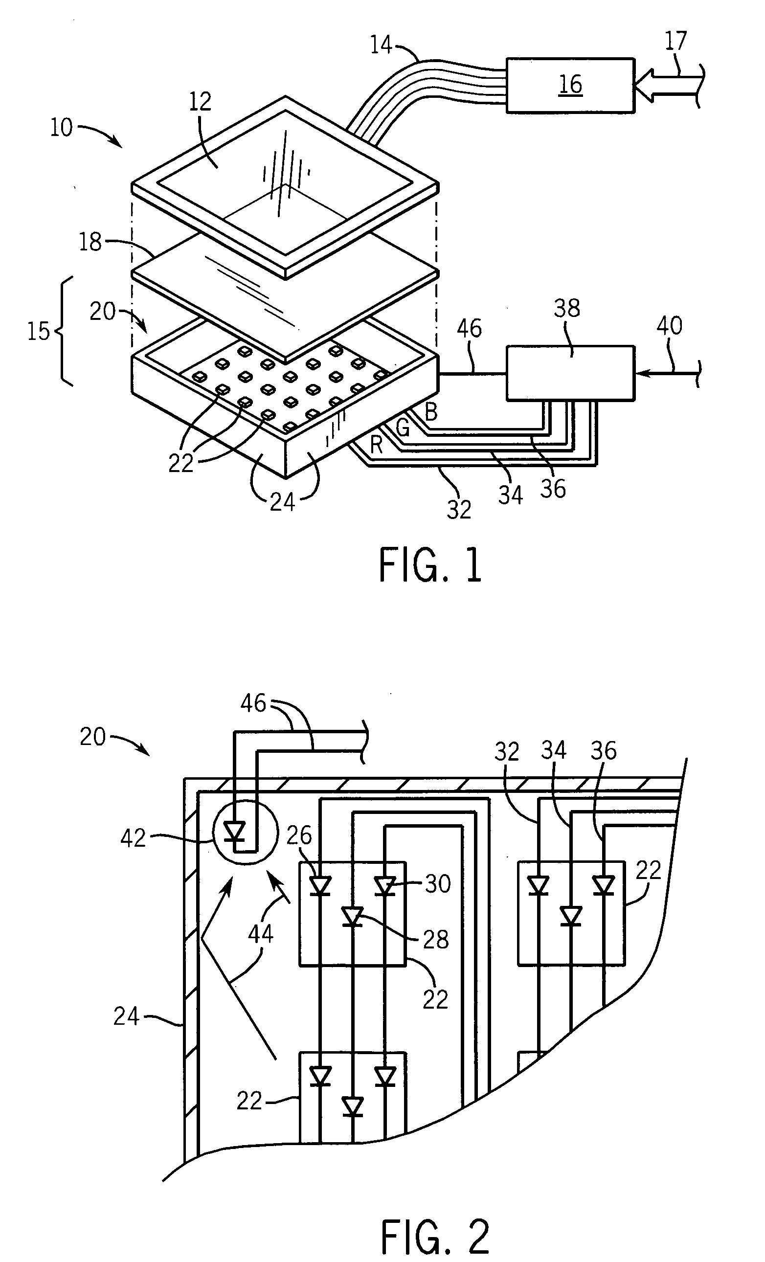
[0042] Referring now to FIG. 1, an avionics display 10 may, for example, include a transmissive liquid crystal display (“LCD”) 12 attached by a cable 14 to avionics electronics 16. Avionics electronics 16 may, for example, provide signals to the avionics display 10 producing graphic representations of indicator gauges and the like based on data 17 received from sensors in the aircraft.

[0043] The LCD screen 12 provides a plurality of electronically controllable pixels for each of three colors: red, green and blue, to provide for a color display when backlit by a multi-spectral and preferably white or nearly white light.

[0044] Positioned behind the LCD screen 12 may be a backlight 15 comprised of a diffuser 18 and an LED array 20. The diffuser 18 positioned between the LED array 20 and the LCD screen 12 serves to spread the light from many point source LEDs in the LED array 20. The diffuser 18, may, for example, also include a lens or holographic screen that collimates or directs th...


PUM


Abstract

A color balanced solid-state backlight provides feedback control of each color using a single photodetector by imposing a modulation pattern on the solid-state lamps revealing individual colors to the photodetector. The photodetector signal provides feedback controlling color balance over a small range of instantaneous brightness less than larger range of average brightness of the display to provide for accurate color balance throughout a large range of average brightnesses.

Description

CROSS-REFERENCE TO RELATED APPLICATIONS STATEMENT REGARDING FEDERALLY SPONSORED RESEARCH OR DEVELOPMENT BACKGROUND OF THE INVENTION [0001] The present invention relates to backlights for instruments such as those using liquid crystal displays and, in particular, to a backlight suitable for avionics and providing a wide range of brightness in a color-balanced white output formed from the combination of light from multiple colored sources. [0002] Graphic displays, such as those employing a liquid crystal display (“LCD”) screen provide a field of pixel elements each of which may be independently controlled to block or pass light, for example, from an underlying backlight. [0003] A common backlight for use with an LCD screen provides a transparent panel edge-lit or backlit by one or more fluorescent tubes. In the edge-lit design, a reflective rear surface of the panel directs the edge illumination towards an LCD screen positioned against a front surface of the panel. The reflective rear...

Claims


Application Information

Patent Timeline
IPC IPC(8): F21V7/04
CPCG09G3/3413G09G2320/0626G09G2320/0633G09G2320/064H05B33/0869G09G2360/145H05B33/0818H05B33/0827H05B33/0857G09G2320/0666H05B45/22H05B45/20H05B45/46
Inventor ZAGAR, PETER A.ELLNER, FREDERICK C.HANSEN, HANS C.
Owner ASTRONAUTICS CORPORATION OF AMERICA
Learn More