
System and method for generating a plurality of models at different levels of abstraction from a single master model

a master model and abstraction technology, applied in the direction of cad circuit design, program control, instruments, etc., can solve the problems of not being well suited to running simulations with real inputs, not being able to test software designed to run on the ic design, and being too slow to simulate relatively slowly

Active Publication Date: 2007-07-19
CADENCE DESIGN SYST INC
View PDF6 Cites 34 Cited by
  • Summary
  • Abstract
  • Description
  • Claims
  • Application Information

AI Technical Summary

Benefits of technology

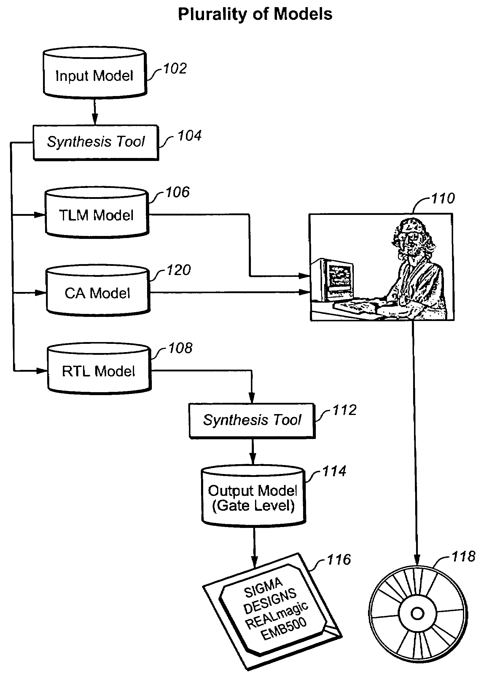
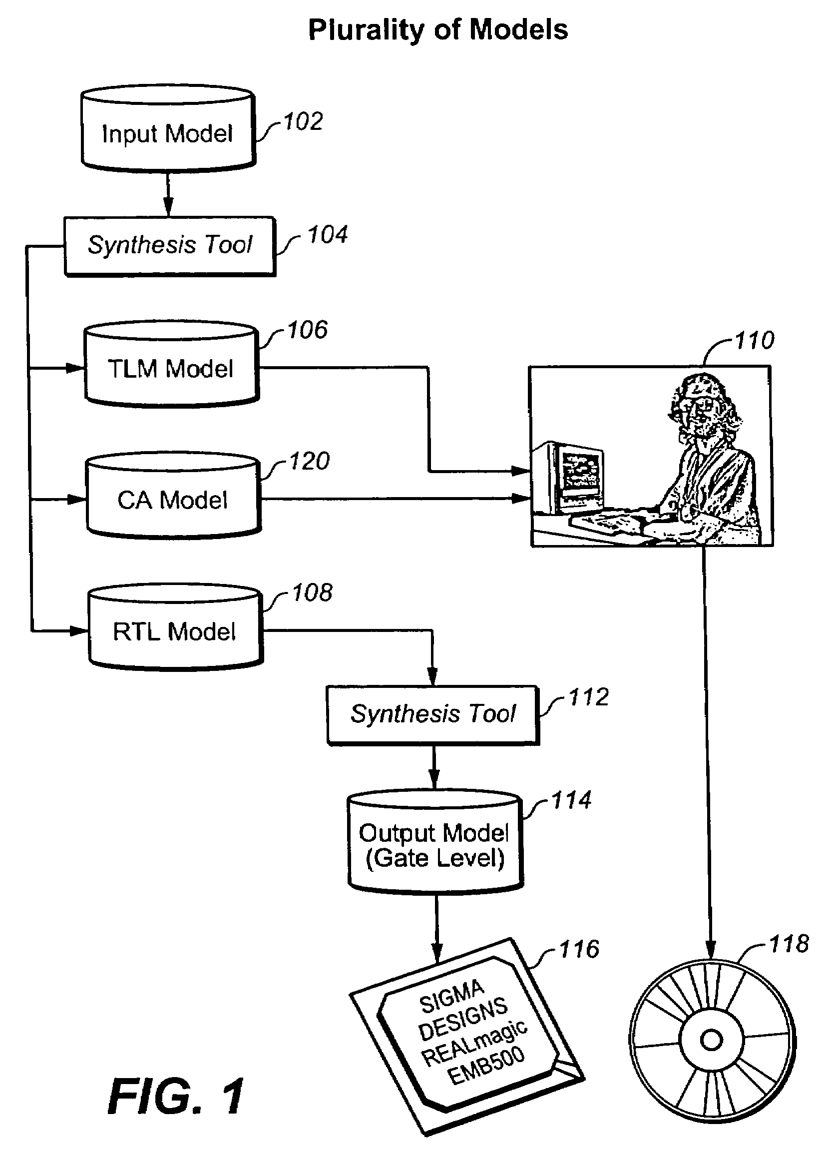
[0009]In one aspect, a method of producing multiple models of a hardware design is provided. A master model of a design is translated to at least first and second models that are functionally equivalent to the master model. The first and second models are at different levels of abstraction from each. The first and second models each includes timing information that is accurate for its level of abstraction.

Problems solved by technology

However all of the detailed timing and synchronization information in RTL models often causes them to simulate relatively slowly.
Unfortunately, this can make them not well suited to running simulations with real inputs.
Often although an emulator runs fast enough for testing the core routines of a circuit; it still may be too slow to test software designed to run on the IC design.
Another problem with using an emulator is that one must have the IC design at a state of development where it is completely specified, and ready to be fabricated into hardware in order to run the design on an emulator.
Since emulators are very expensive, some companies just skip the emulation step and fabricate the actual chip, and test the software at full hardware speed.
In view of the costs of emulation and the time required for more thorough simulation, they take the risk that the resulting chip will function adequately even though testing, particularly software testing, has been cut short.
If there are bugs that are too severe to work around using software, then the chip hardware may have to be changed, which typically requires a re-design and fabrication of a new chip at significant cost in time and money.

Method used


Image

  • System and method for generating a plurality of models at different levels of abstraction from a single master model
  • System and method for generating a plurality of models at different levels of abstraction from a single master model
  • System and method for generating a plurality of models at different levels of abstraction from a single master model

Examples


example

[0036]The following is a code example of an input master model code and its translation to an RTL model code and to transaction accurate model code.

[0037]Consider the following example of input master model code, which corresponds to an input master model 102 of FIG. 1:

class alu: public sc_module { ... SC_THREAD(adder); SC_THREAD(multiplier); ... void adder( ) {  while (true)   if (ENABLE && OPCODE == ADD) {    port_OUT = port_IN1.read( ) + port_IN2.read( );   }  } }}

[0038]This code describes an adder. Whenever ENABLE is true, and the OPCODE has the value ADD, the system will calculate the sum of the value on the input port in1 and input port in2, and drive the result to output port OUT. There is no specification of time in this code; only behavior.

[0039]There are many possible implementations of the behavior that are consistent with this specification. Differing implementations might perform the operation more quickly than another, or use less power to do the calculation (better ba...


PUM


Abstract

A method of producing multiple models of a hardware (integrated circuit) design including: translating a master model of a design of the integrated circuit to at least first and second models that are functionally equivalent to the master model and that are at different levels of abstraction from each, other and in which each of the first and second models includes integrated circuit timing information that is accurate for its level of abstraction.

Description

CROSS REFERENCE TO RELATED APPLICATIONS[0001]This application relates to the following commonly assigned patent applications: System and Method for Synthesis Reuse, filed Dec. 30, 2005; System and Method for Verification Aware Synthesis, filed Dec. 30, 2005; and System and Method for Incremental Synthesis, filed Dec. 30, 2005, each of which is expressly incorporated herein in its entirety by this reference.BACKGROUND OF THE INVENTION[0002]1. Field of the Invention[0003]The invention relates in general to the design of integrated circuits and more particularly, to the use of modes at different levels of abstraction during the design of integrated circuits.[0004]2. Description of the Related Art[0005]Modern circuit design has evolved into a specialized field often referred to as electronic design automation in which computers and computer aided design (CAD) techniques are used to automate the integrated circuit (IC) design process. An IC design process typically begins with an enginee...

Claims


Application Information

Patent Timeline
Patent Type & Authority Applications(United States)
IPC IPC(8): G06F17/50
CPCG06F17/505G06F17/5045G06F30/327G06F30/30
Inventor WATANABE, YOSINORILAVAGNO, LUCIANOKONDRATYEV, ALEX
Owner CADENCE DESIGN SYST INC
Learn More