
Time determination method and system based on hierarchical control, and medium

A technology of hierarchical control and determination method, applied in the field of signal processing, can solve the problem that wireless timing signals cannot be directly connected to the internal network, etc., and achieve the effect of both timing integrity monitoring, time synchronization, and high-precision measurement.

Active Publication Date: 2021-07-20
北京卫星导航中心
View PDF3 Cites 1 Cited by
  • Summary
  • Abstract
  • Description
  • Claims
  • Application Information

AI Technical Summary

Problems solved by technology

However, in some fields, according to relevant systems and regulations, the wireless timing signal cannot be directly connected to the internal network. At this time, it is necessary to redesign the scheme of the time determination system

Method used


Image

  • Time determination method and system based on hierarchical control, and medium
  • Time determination method and system based on hierarchical control, and medium
  • Time determination method and system based on hierarchical control, and medium

Examples


Embodiment 1

[0056] One upper-level node needs to provide time services for multiple lower-level nodes. However, the main TS cannot integrate too many optical fiber bidirectional time-frequency transfer calculation modules and E1 link time calculation modules. At this time, one optical fiber bidirectional time-frequency transfer solution device and one E1 link time solution device can be designed. In these two devices, N optical fiber two-way time-frequency transmission and calculation modules and N E1 time calculation modules are integrated according to requirements, and their function is to provide E1 time services for N lower-level nodes. At this time, the design scheme of each node is as follows Figure 8 shown. One optical fiber two-way time-frequency transfer solution device and one E1 link time solution device realize time synchronization through IRIG-B (DC) code and main TS respectively, and then transmit to the main TS of the subordinate node through optical fiber and E1 link re...

Embodiment 2

[0058] According to actual needs, each node can be image 3 Based on the basic design scheme shown, some equipment and functions are added. For example, one master TS can be added to each node, so that each node includes two master TSs and one backup TS, so as to prevent the time service of the node from being interrupted when one master TS goes offline due to a fault.

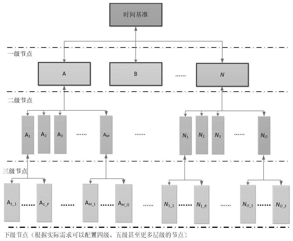
[0059] The second aspect of the present invention provides a time determination system based on hierarchical control. The hierarchical control includes: K-level nodes, K is a positive integer; wherein each node in the i-th level node is configured with at least one primary TS and a corresponding standby TS; when i is 1, the i-th level node In each node in , the main TS is synchronized with the time reference; when i is a positive integer from 2 to K, in each node in the i-th level node, the main TS is connected to the first-level node through a wired timing link The main TS of the corresponding node in the i...


PUM


Abstract

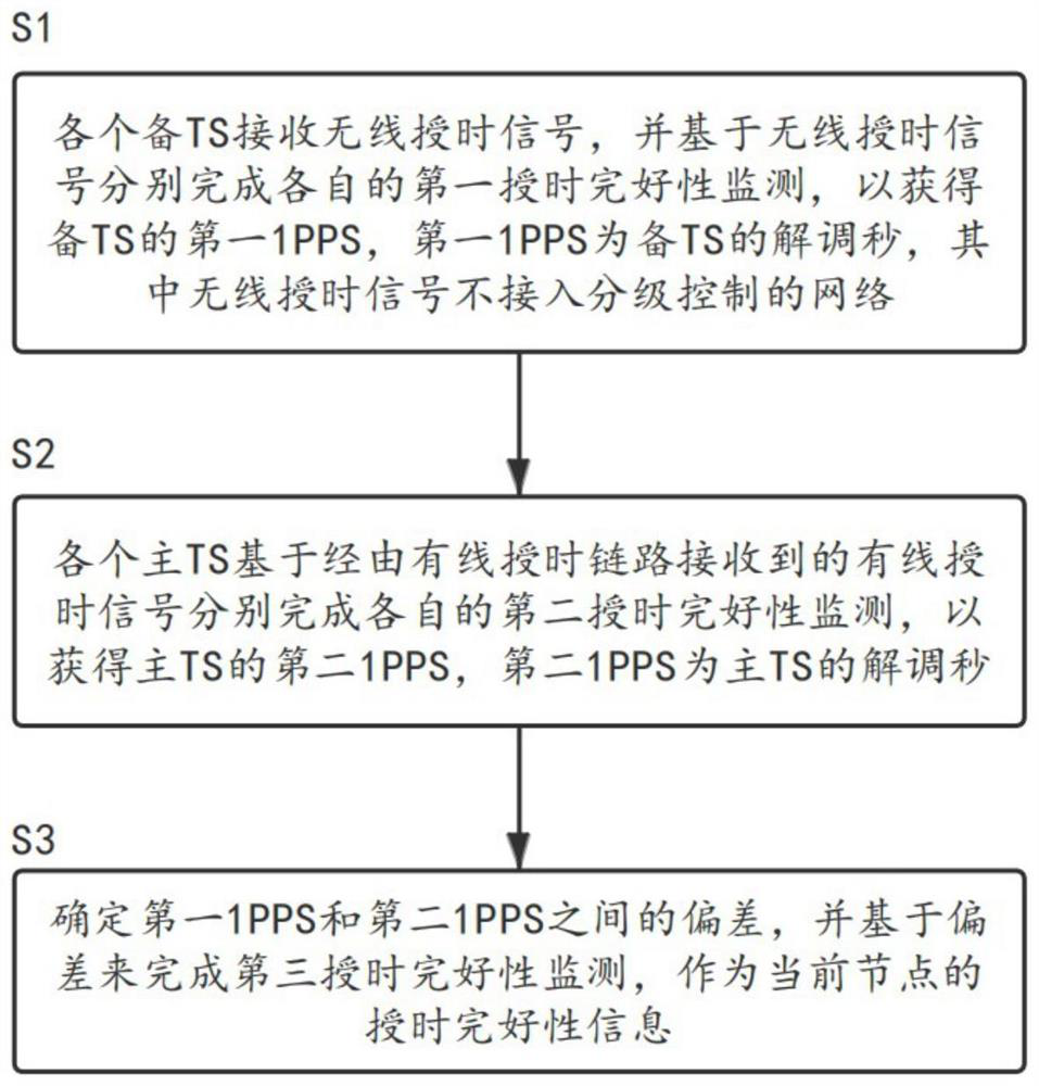
The invention provides a time determination method and system based on hierarchical control and a medium. The time determination method comprises the following steps: S1, each standby TS receives a wireless time service signal and completes respective first time service integrity monitoring based on the wireless time service signal so as to obtain a first 1PPS of the standby TS, the first 1PPS is a demodulation second of the standby TS, and the wireless time service signal does not access a hierarchical control network; S2, each main TS completes respective second time service integrity monitoring based on a wired time service signal received by the wired time service link so as to obtain a second 1PPS of the main TS, and the second 1PPS is a demodulation second of the main TS; and S3, a deviation between the first 1PPS and the second 1PPS is determined, and third time service integrity monitoring is completed based on the deviation as time service integrity information of the current node.

Description

technical field [0001] The invention relates to the field of signal processing, in particular to a time determination method and system based on hierarchical control. Background technique [0002] The time determination system (also known as "time unification system") is a complete system composed of various electronic devices that provides standard time signals and standard frequency signals to realize the unification of time and frequency of the entire system. The time determination system consists of two parts: time service and user. User terminal equipment is generally called time-unified terminal equipment, or simply "time-unified" terminal equipment. [0003] The time reference established and maintained by the timekeeping system, and the time information representing the time reference is transmitted to the user through the time service system. The function of the time system terminal equipment is to receive the timing signal to keep its own time and time reference ...

Claims


Application Information

Patent Timeline
Patent Type & Authority Applications(China)
IPC IPC(8): H04J3/06
CPCH04J3/0667H04J3/0638
Inventor 伍贻威张悦肖胜红王茂磊潘峰李冲王世超杨斌缑东刚杨思佳李曼曼宋倩喻金张晓博魏春苗
Owner 北京卫星导航中心
Learn More