
Method of determining the pressure of a gas mixture in a vacuum container by means of absorption spectroscopy

a technology of vacuum container and gas mixture, which is applied in the direction of material analysis through optical means, measurement devices, instruments, etc., can solve the problems of difficult to determine correctly, difficult to determine the length of the beam path, and high cost of dry air flushing the chamber after each vial, etc., to achieve low cost, high reliability, and the effect of low cos

Inactive Publication Date: 2007-07-19
LAVISION
View PDF1 Cites 7 Cited by
  • Summary
  • Abstract
  • Description
  • Claims
  • Application Information

AI Technical Summary

Benefits of technology

[0012]It is therefore the object of the invention to provide a method of determining the pressure of a gas or gas mixture in a vacuum container by means of absorption spectroscopy that is located in an environment also containing the gas to be measured, but at a pressure different than that prevailing in the vacuum container, said method involving little expense on the one side and ensuring high reliability with regard to determining the gas to be measured in the vacuum container (vial) and being moreover cheap to carry out.
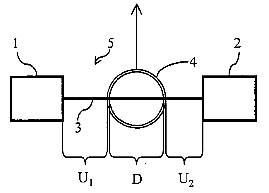
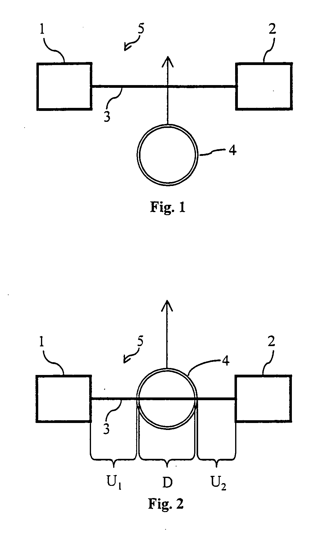
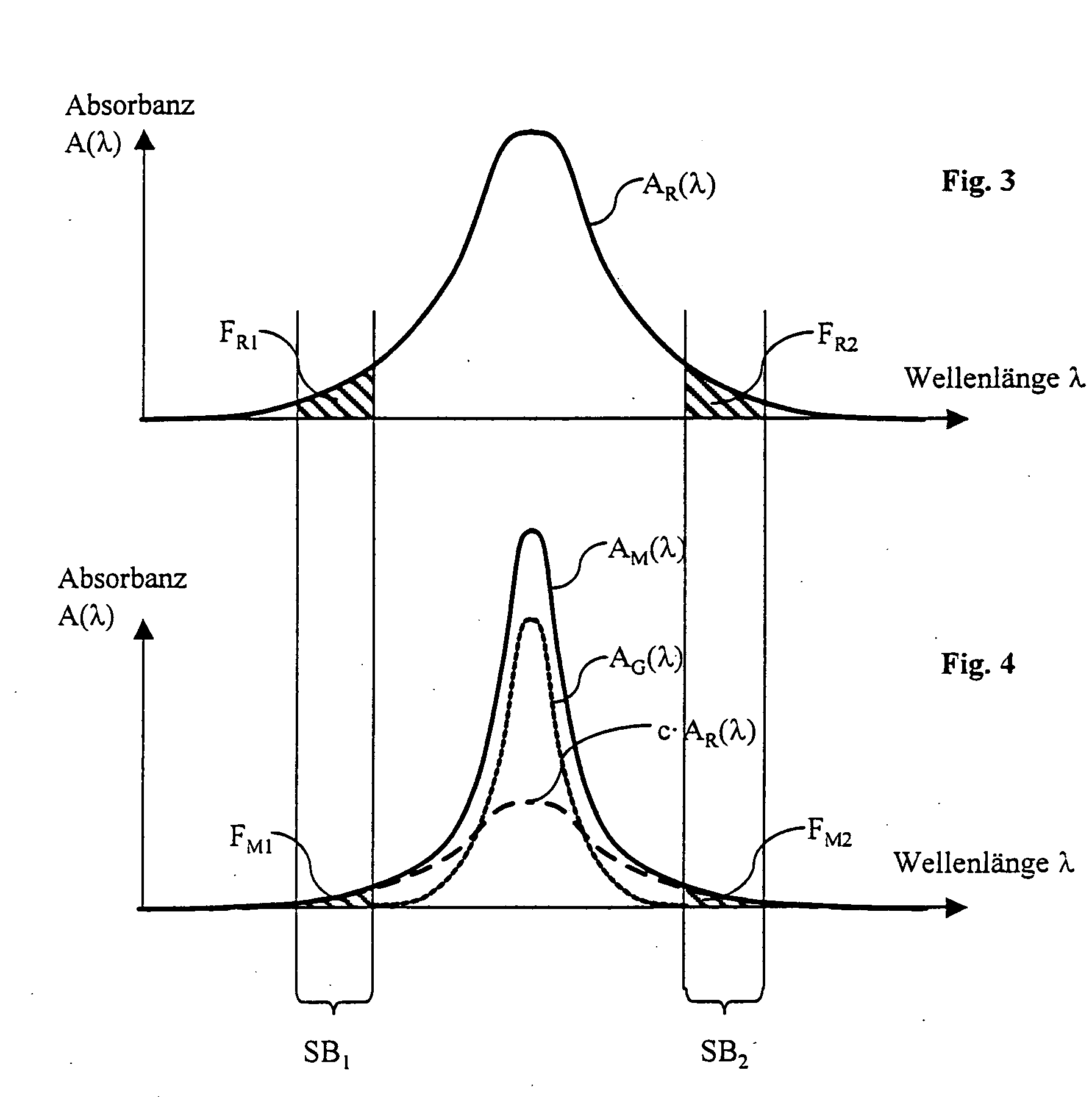
[0016]Determining for the absorption curve is on the one side the density of the water molecules or the height of the partial pressure of the water vapor and on the other side the path length, i.e., the length between the laser emitter and the laser detector, and the pressure and temperature. This is to say that the absorbance is proportional to the density of the molecules and also proportional to the path length of the laser light, meaning of the path length of the absorption. The line width Δ(λ) of the absorption curve, by contrast, is independent of these variables but instead dependent on the pressure p, the temperature T and the composition of the gas. As already explained herein above, pressure and temperature should be the same everywhere except for the vacuum container where negative pressure prevails. The path length of the air in both measurements of AR(λ) and AM(λ) however only differs by the diameter of the vacuum container (vial). As already explained, ambient p and T are assumed to be constant. Taking more particularly into consideration the fact that the line width depends on the pressure, and that accordingly the absorption curve of AM(λ) and AR(λ) is wider that the absorption curve AG(λ), this means that the absorption curves AM(λ) and AR(λ) are greater than 0 in the border zones, with AG(λ) being almost equal to 0 in these border zones. The differences between AM(λ) and AR(λ) are only in the differing path length because of the container placed in the beam path, since all the other factors are assumed to be equal or constant. Accordingly, the course of the absorption curves of AM(λ) and of AR(λ), that is, the configuration or shape of these curves, is the same. Meaning, the curves only differ by a proportionality factor c in the form ofc=AM(λ)AR(λ)in the border zones of the absorption curves. The possibility of having AM(λ) coinciding with AR(λ) through the factor c allows for eliminating the influence of the ambient air onto the measurement. This allows determining from AM(λ) and AR(λ) the absorption spectrum AG(λ) in the container according to AG(λ)=AM(λ)−c·AR(λ).

Problems solved by technology

Flushing the chamber with dry air after each vial is expensive in terms of time and cost since a considerable amount of energy is needed to dry the air.
Moreover, it must be ensured that the chamber is tight since leakage may corrupt the measurement.
The length of the beam path is also very difficult to determine since the entire distance between laser and detector are also included in U, that is to say, also and in particular the measurement length within the various instruments so that U is almost impossible to determine correctly.
This cannot be ensured either, this being the reason why this method of measurement is cheaper than the first measurement method mentioned but is also much more inaccurate or the expenditure in terms of measuring technique is much higher than with the first method.

Method used


Image

  • Method of determining the pressure of a gas mixture in a vacuum container by means of absorption spectroscopy
  • Method of determining the pressure of a gas mixture in a vacuum container by means of absorption spectroscopy
  • Method of determining the pressure of a gas mixture in a vacuum container by means of absorption spectroscopy

Examples


Embodiment Construction

[0024]Referring to the example, it will be assumed herein after that the water vapor partial pressure in the vacuum container is to be determined. Of course, any other gas contained in the environment and in the container can be determined. The important point however is that the ambient pressure is substantially higher than that prevailing in the container.

[0025]Referring to FIG. 1, the laser is indicated at 1, the laser detector for measuring the laser power at 2, the laser beam at 3, the vacuum container at 4 and the ambient air at 5. In the test array of FIG. 1, the laser beam does not pass through the vacuum container 4, that is to say that what is determined with this test array is the absorption curve AR(λ). The test array of FIG. 2 serves to determine the absorption curve AM(λ). Here, the vacuum container 4 has been placed entirely into the beam path 3, that is to say that the laser beam traverses the container exactly in the center thereof. The distance traveled by the beam...


PUM


Abstract

The subject matter of the invention is a method of determining, by means of absorption spectroscopy, the pressure of a gas or gas mixture in a vacuum container located in an environment that also contains the gas to be measured, but at a pressure different from that in the vacuum container, comprising a laser and a laser detector, the absorption curve AR(λ) of the gas to be determined being determined in the beam path between laser and detector in a first step, the vacuum container being placed into the beam path and the absorption curve AM(λ) of the gas to be determined being determined in the beam path into which the vacuum container has been placed in a second step, that the absorption curve AR(λ) is made to coincide by compression with the absorption curve AM(λ) outside of the absorption curve of the gas to be measured, the extent of compression being determined by a proportionality factor c, the following relation applying for determining the gas to be measured in the vacuum container:AG(λ)=AM(λ)−c·AR(λ).

Description

FIELD OF THE INVENTION[0001]The invention relates to a method of determining the pressure of a gas or gas mixture in a vacuum container by means of absorption spectroscopy.[0002]In medical engineering, powder products are often stored in vials. In manufacturing or filling such type vials, the problem arising is that it must be made certain that a negative pressure prevails inside these vials in order to ensure that the product stored in the vial will not be damaged by air penetrating into the vial during storage.[0003]This means that such type vials must be checked to see whether certain ambient gases such as water vapor e.g., are contained in these vials in order to see from the water vapor concentration in the vial whether the vacuum is still intact.[0004]In this context, two measurement methods of determining the hydrogen partial pressure or the gas volume in the vial are known.DESCRIPTION OF THE PRIOR ART[0005]According to known prior art (WO 2005 / 040753 A2), a chamber is provid...

Claims


Application Information

Patent Timeline
IPC IPC(8): G01N21/00
CPCG01L11/02
Inventor BERG, THOMAS
Owner LAVISION
Learn More