
Varactor diode alternative circuit

a technology of alternative circuits and varactor diodes, which is applied in the direction of continuous tuning, oscillation generators, resonance circuit tuning, etc., can solve the problems of affecting the useful signal, and causing signal distortion, so as to achieve effective avoidance of intermodulation interference, increase the capacitance, and reduce the capacitance

Inactive Publication Date: 2007-07-19
ROBERT BOSCH GMBH
View PDF4 Cites 31 Cited by
  • Summary
  • Abstract
  • Description
  • Claims
  • Application Information

AI Technical Summary

Benefits of technology

The present invention provides a varactor diode alternative circuit that can effectively avoid intermodulation interferences and reduce the need for a boost chopper, which can reduce interference suppression and lower expenditure. The circuit can be used in electrical units, especially battery-operated units, without the need for a higher tuning voltage. The circuit can also be implemented in an integrated circuit form. Overall, the invention provides a more efficient and cost-effective solution for tuning the signal voltage in oscillator circuits.

Problems solved by technology

The same also applies in connection with integrated circuits, which often have to be supplied, in the course of smaller semiconductor structures, with ever lower operating voltages, so that a subsequent voltage increase to achieve higher control voltages for the varactor diode would usually be too costly.
In the case of large signal voltage levels, the capacitance of the varactor diode accordingly fluctuates in time with the useful signal, that is to be processed in the oscillator circuit, so strongly that distortions in the signal come about, especially intermodulation.
In this connection, interference signal components may be created that impair the useful signal, and cannot be subsequently filtered out.
This effect occurs particularly strongly in diodes having a large capacitance ratio, since, in this instance, even smaller signal voltages are sufficient in order to generate a no longer acceptable interference signal strength.

Method used


Image

  • Varactor diode alternative circuit
  • Varactor diode alternative circuit
  • Varactor diode alternative circuit

Examples


Embodiment Construction

[0018] Varactor diodes are also used in circuits in which the capacitance-controlling signal is not a direct voltage, but an alternating voltage, for instance, for frequency modulation of a high-frequency signal as a function of a low-frequency alternating voltage, such as an audio signal. Generally, the frequency of the capacitance-controlling signal deviates clearly from the frequency of those signals which are processed in the controlled signal path, for instance, in a frequency-variable oscillator circuit.

[0019] The activation of the alternative circuit according to the present invention by an alternating voltage is also possible, and lies within the scope of the present invention. From here on, for the better understanding of the function, the capacitance-controlling voltage is frequently designated as direct voltage, without excluding thereby comparable applications using capacitance-controlling alternating voltages.

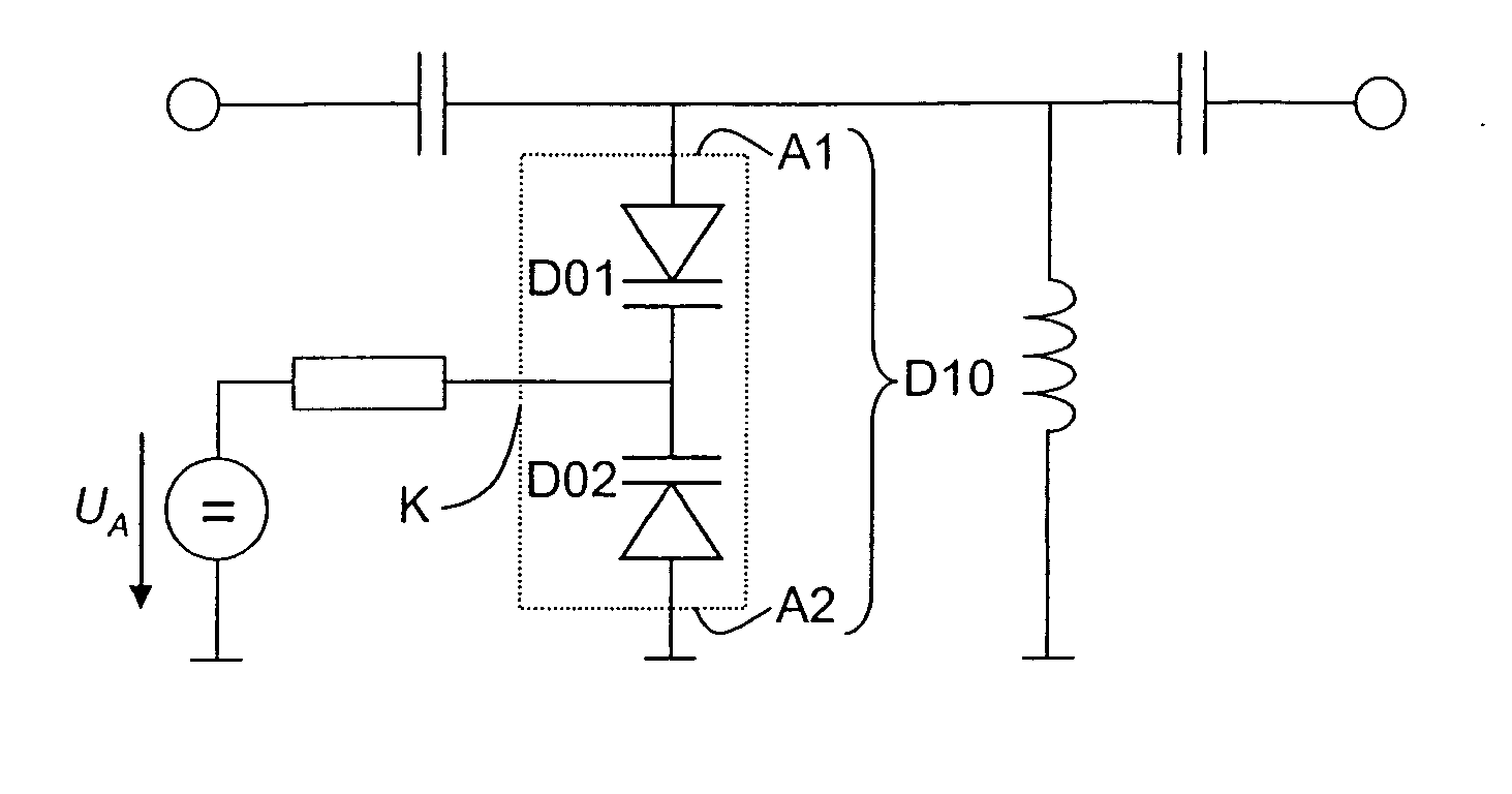
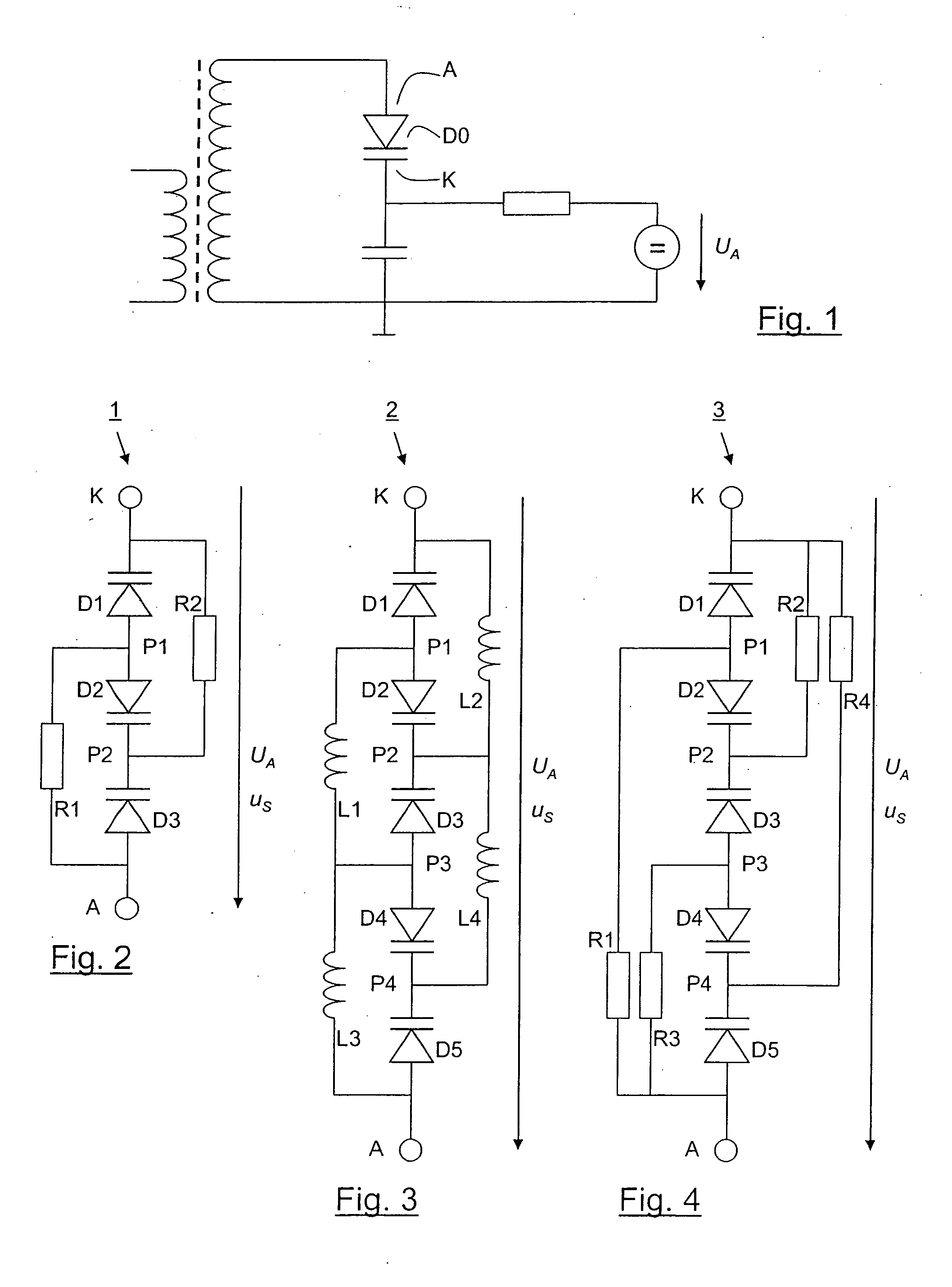
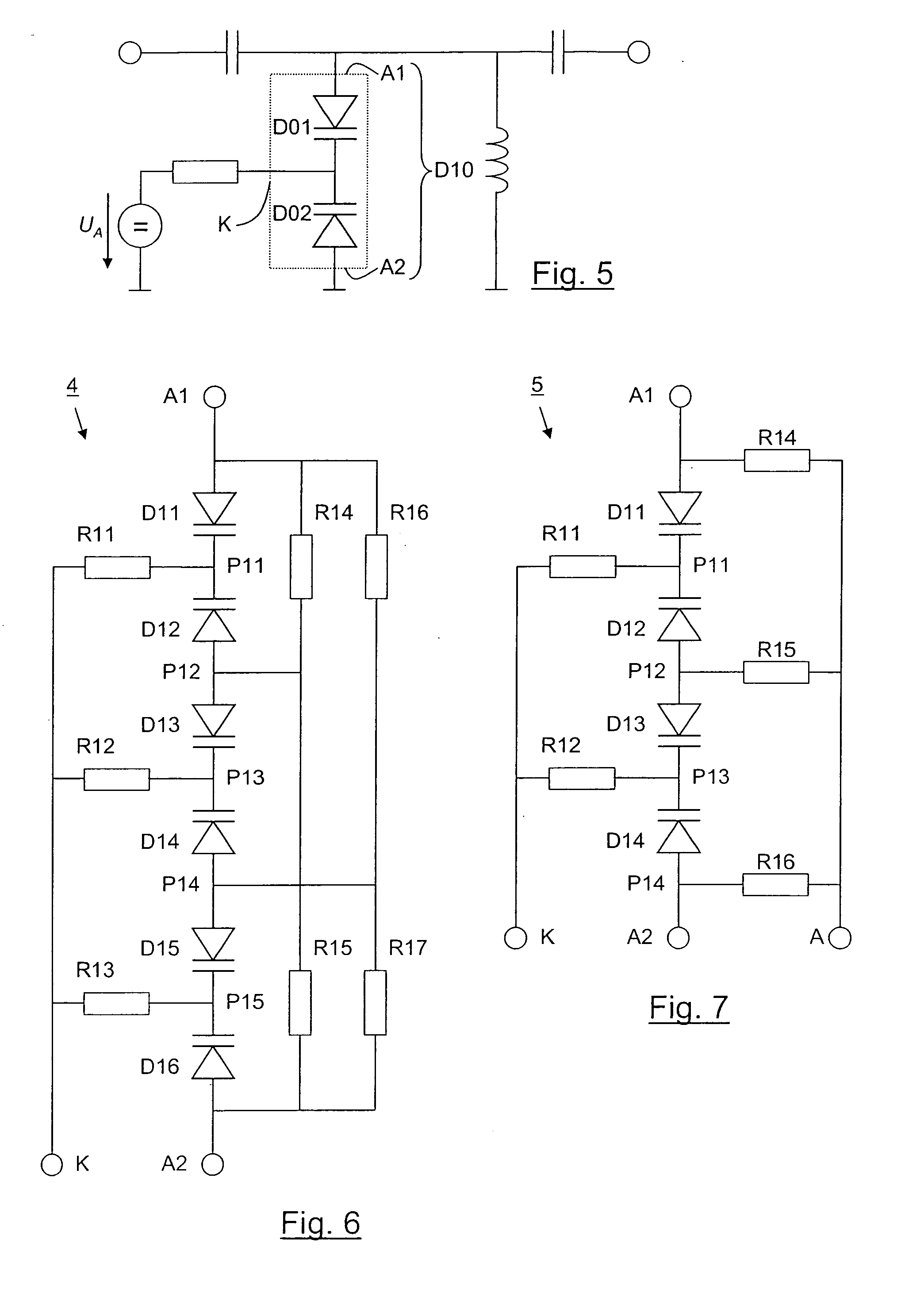
[0020]FIG. 2 shows, for example, a circuit diagram of an os...


PUM


Abstract

A varactor diode alternative circuit having at least three varactor diodes that are in each case connected in series alternatingly opposite to one another and a resistor network and / or inductor network, which has the effect that at each of the varactor diodes, a control voltage supplied to the circuit for adjusting the capacitance is present at least approximately at full extent, and an alternating voltage that is applied at the series connection of the varactor diodes, which is at a higher frequency compared to the control voltage, is distributed preferably at least approximately uniformly to the varacter diodes. A varactor diode alternative circuit has the advantage that even for a smaller, or not larger, or not substantially larger tuning voltage compared to the amplitude of a signal voltage that is to be processed in the oscillator circuit that has the alternative circuit, the reactions of the signal voltage on the set capacitance of the varactor diode alternative circuit remain negligible, or at least low. Thus, intermodulation interferences are effectively avoided. In addition, the circuit may be advantageously used in an electrical unit in which only one small operating voltage is available, for instance, in a battery-operated unit.

Description

BACKGROUND INFORMATION [0001] Conventionally, varactor diodes may be used for tuning oscillator circuits. Varactor diodes are diodes that have a particularly pronounced dependence of their blocking capacitance on the electrical voltage that is applied. By applying an electrical direct voltage to the varactor diode, this effect may be used to set its capacitance and thereby the resonant frequency or other parameters of an oscillator circuit. [0002] In order to be able to cover a large frequency range, using these oscillator circuits or filters, it may be advantageous if the varactor diodes used have a large capacitance ratio or a large capacitance swing, that is, the relative difference between the smallest and the largest capacitance value that may be set is particularly great. In particular, the entire available capacitance swing of the varactor diodes should be achievable even when having low control voltages applied, so that the entire range may be utilized in the case of battery...

Claims


Application Information

Patent Timeline
Patent Type & Authority Applications(United States)
IPC IPC(8): H03B5/12H03J3/18
CPCH03J3/185
Inventor KOTTSCHLAG, GERHARD
Owner ROBERT BOSCH GMBH
Learn More