
Vehicle front interior structure

a technology for interior structure and vehicle, applied in the direction of vehicular safety arrangments, roofs, pedestrian/occupant safety arrangements, etc., can solve problems such as severe injuries, reduce the stiffness of the structure, increase the braking distance, and slow down the deceleration of objects

Inactive Publication Date: 2007-07-19
VOLVO CAR CORP
View PDF13 Cites 13 Cited by
  • Summary
  • Abstract
  • Description
  • Claims
  • Application Information

AI Technical Summary

Benefits of technology

The invention is a vehicle front interior structure that improves impact energy absorbance compared to conventional structures, particularly in the event of a collision with a pedestrian. The technical features of the invention include an air flow distribution duct divided into at least two sections connected by a flexible joint, a dashboard member that detaches from the vehicle body when exposed to a force exceeding a pre-determined limit, a windshield support member that absorbs impact energy, and an air flow main duct that is flexible and at least partly formed in a flexible material. These features allow for efficient impact energy distribution and slow down the deceleration of an impacting object, reducing injuries in a collision with a pedestrian.

Problems solved by technology

Whereas both the hood and the windshield are relatively flexible and therefore can absorb a great deal of the impact energy, the interface between the hood and the windshield generally is a rigid zone which therefore may cause severe injuries if hit.

Method used


Image

  • Vehicle front interior structure
  • Vehicle front interior structure
  • Vehicle front interior structure

Examples


Embodiment Construction

)

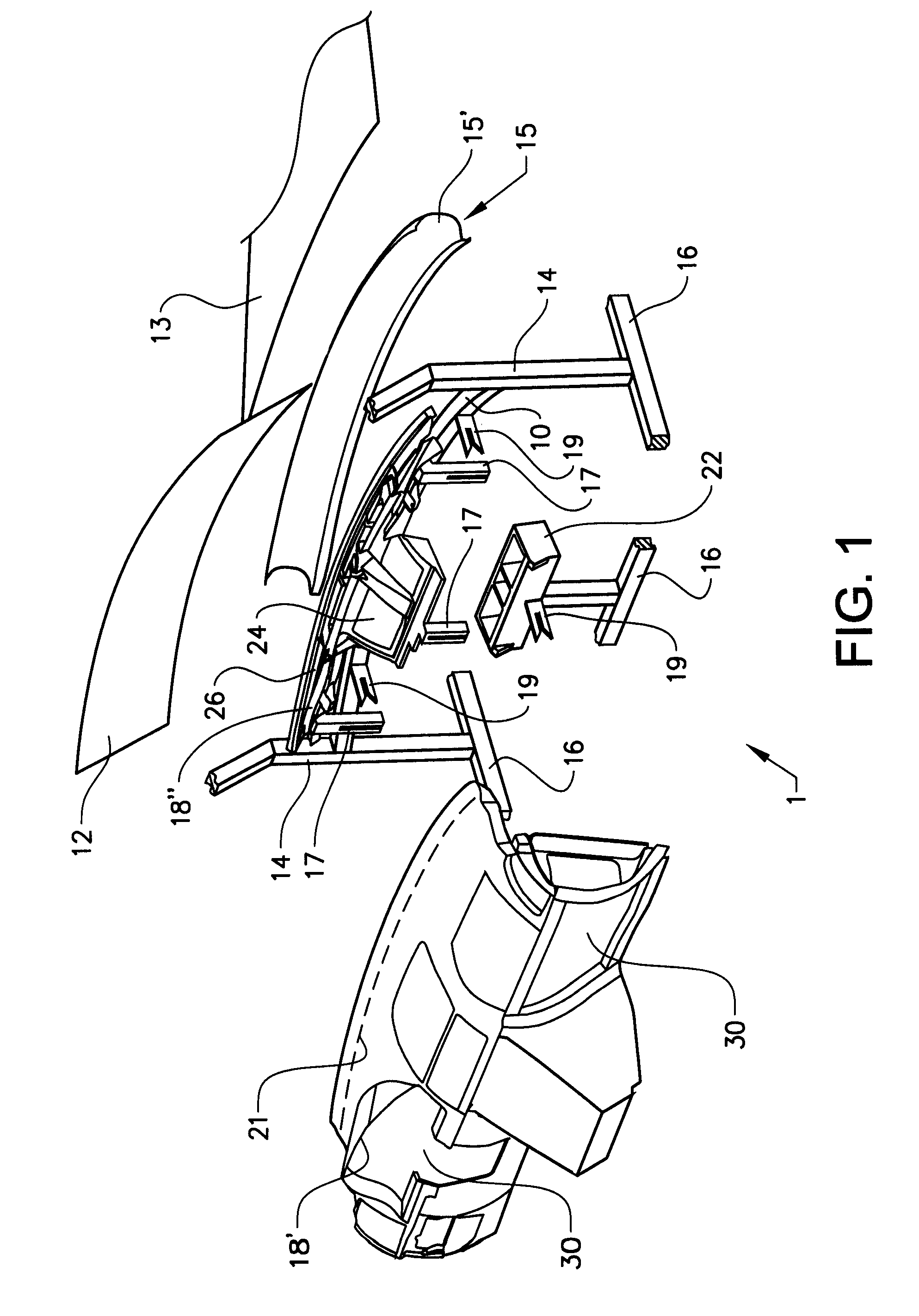
[0022]FIG. 1 schematically shows in an exploded perspective view a vehicle front interior structure 1 according to a preferred embodiment of the invention. A cross member 10 extends transversely at some distance below a windshield 12 between the A-pillars 14 of a schematically shown vehicle body 16. The cross member 10 provides structural rigidity and support to the vehicle and it also supports a windshield supporting member 15 comprising a curved flange 15′. A hood 13 is also shown in FIG. 1. The front interior structure 1 further comprises a first, outer, dashboard member 18′; a second dashboard member 18″ forming main air flow ducts 24 and air flow distribution ducts 26; and a heating, ventilating and air conditioning unit (HVAC-unit) 22. The HVAC-unit 22 is principally a solid box containing air treatment equipment. The main ducts 24 lead the treated (e.g. heated) air from the HVAC-unit 22 in a diagonal forward / upwards direction to the distribution ducts 26 arranged in parallel...


PUM


Abstract

The invention concerns a vehicle front interior structure comprising an air flow distribution duct arranged essentially parallel with a windshield. The invention is characterized in that the distribution duct is divided into at least two sections connected by a flexible joint that extends in a direction essentially across the distribution duct.

Description

CROSS-REFERENCE TO RELATED APPLICATION [0001] This application claims foreign priority benefits under 35 U.S.C. § 119(a)-(d) to European Application No. 06100401.6, filed Jan. 16, 2006, which is hereby incorporated by reference in its entirety. BACKGROUND OF THE INVENTION [0002] 1. Field of the Invention [0003] This invention relates to impact energy absorbance properties of a vehicle front interior structure, in particular in the event of a collision with a pedestrian. [0004] 2. Background Art [0005] Vehicles have for many years been designed to protect the occupants of the vehicle. Another important aspect in the design of vehicles is to prevent, or at least reduce, injuries of pedestrians in the event of a collision. Most of the disclosed designs focus on the front end or hood (bonnet) structure of the vehicle. An important aspect in this context is to reduce the impact to the head of a pedestrian. In a collision with an adult pedestrian the head of the pedestrian is likely to hi...

Claims


Application Information

Patent Timeline
Patent Type & Authority Applications(United States)
IPC IPC(8): B60K37/00B60R21/34
CPCB60H1/0055B62D25/145B60R2021/343
Inventor ERLINGFORS, MATSJONSSON, TONYBENGTSSON, THOMAS
Owner VOLVO CAR CORP
Learn More