
Temperature regulating suit

a temperature regulation and suit technology, applied in the field of temperature regulation of the body, can solve the problems of garments not being suitable for heating patients, not being suitable for surgery, and not being suitable for use on patients during surgery

Inactive Publication Date: 2007-07-12
MEDISUIT
View PDF1 Cites 32 Cited by
  • Summary
  • Abstract
  • Description
  • Claims
  • Application Information

AI Technical Summary

Benefits of technology

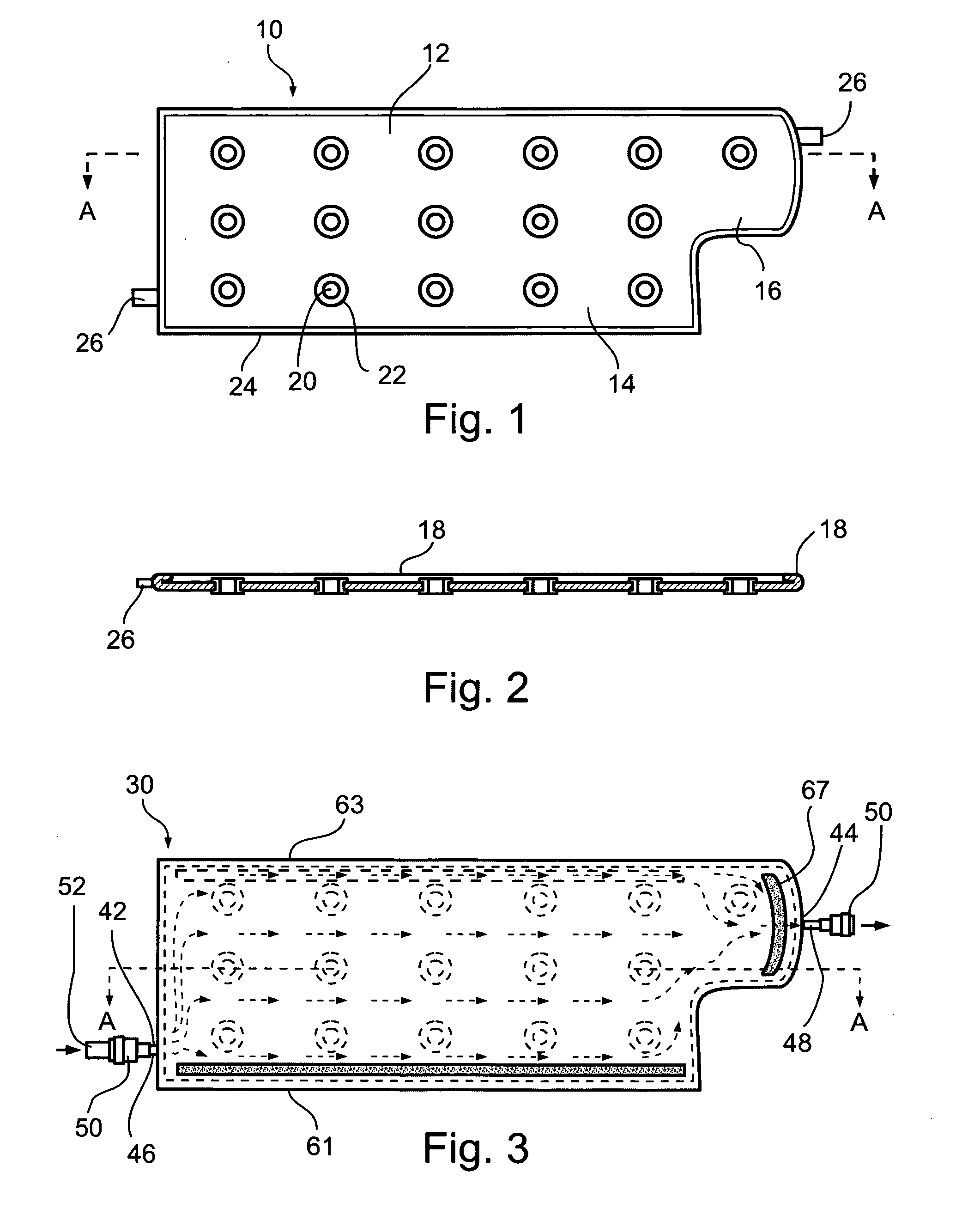
[0033] In embodiments, the inlet conduits connect the heat transfer components to a fluid source and the plurality of outlet conduits connect the heat transfer components to a fluid disposal point, and the control unit controls the temperature of fluid flowing via the plurality of inlet conduits into the heat transfer components, thereby controlling the temperature of the heat transfer components.
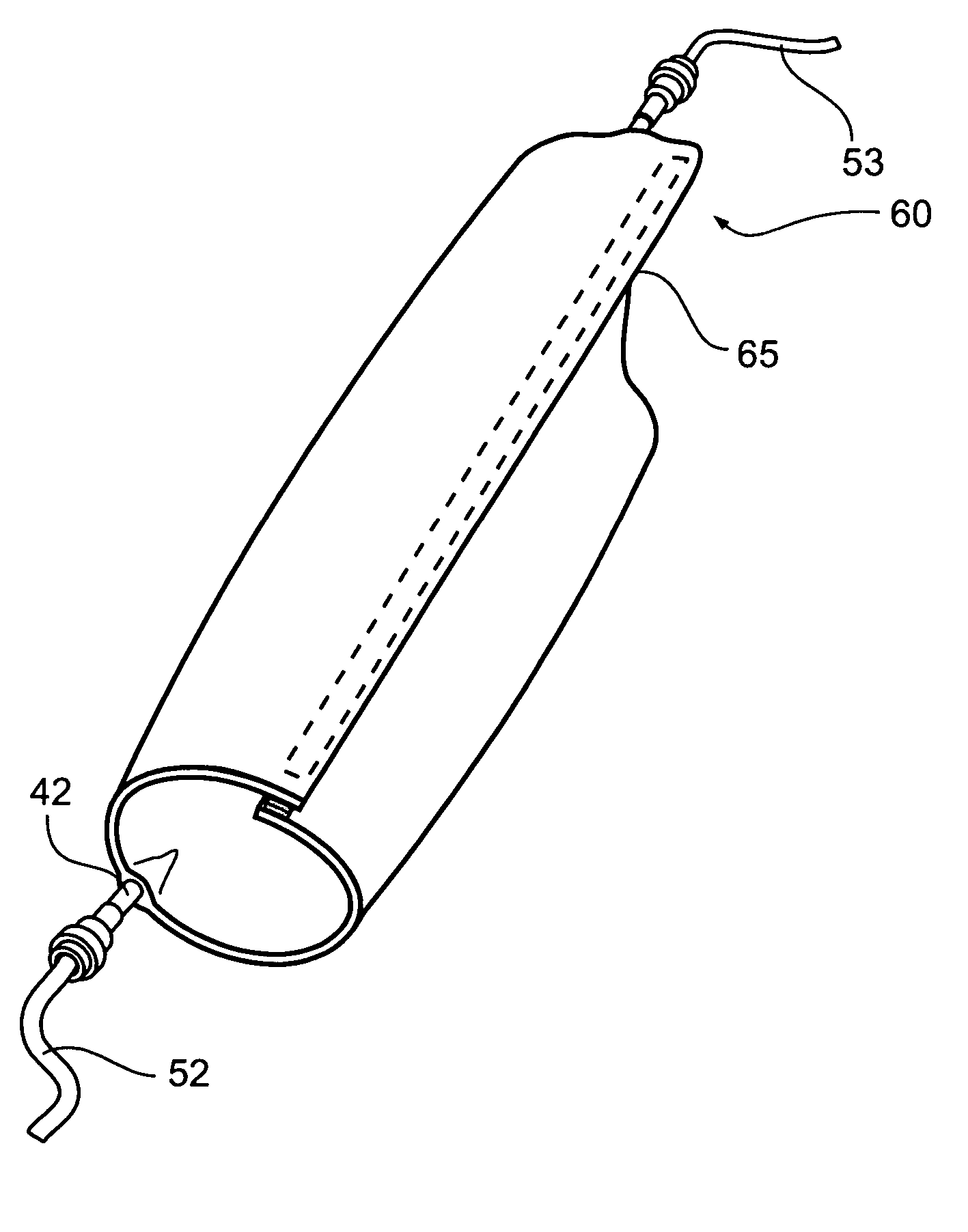
[0037] According to the teachings of the present invention, there is also provided a valve substantially of two strips of flexible material conjoined at two sides so as to substantially define a flattened tube. As a self-sealing intake valve, a fluid source is placed between the two strips at the upstream end of the flattened tube where the downstream end of the valve protrudes into the bulk of a fluid. Fluid flows from the fluid source into the flattened tube, pushing apart the two strips and flowing out the downstream end of the flattened tube. Due to the pressure applied by the bulk of the fluid onto the downstream end of the flattened tube (and preferably also a self-affinity of the material), fluid cannot back-flow through the downstream end of the tube. Further, if the downstream end of the flattened tube is immersed in a fluid, the fluid pressure keeps the two strips pressed tightly together ensuring a seal. As a self-sealing outlet valve, a fluid drain is placed between the two strips from the downstream end of the flattened tube to proximity with the upstream end of the flattened tube so that the fluid drain maintains the two strips at the upstream end separated and non-sealed where the upstream end of the valve protrudes into the bulk of a fluid. In such a position, fluid can freely drain from the upstream end of the flattened tube through the fluid drain out through the downstream end of the flattened tube as long as the fluid drain is in position. When the fluid drain is withdrawn whether by accident or by design, out through the downstream end to the extent that the fluid drain does not maintain the two strips at the upstream end separated, then the pressure applied by the bulk of the fluid onto the upstream end of the flattened tube (and preferably also a self-affinity of the material), closes off the tube preventing further fluid flow through the tube.

Problems solved by technology

Frail or elderly patients may require heating.
While the contents of an operating room may be sterilized prior to use, operating room personnel may inadvertently introduce bacteria or other microorganisms into the operating room.
Known heating devices are disadvantageous, in not providing even heating of a patient, are difficult to control especially during a long surgical procedure, and pose the risk of causing burn wounds to the patient.
The garment is, however, neither suitable for heating a patient nor suitable for use on a patient during surgery.
Although the one-piece garment is intended to be suitable for all patients, and ten different sizes of the one-piece garment are available for adults, children, and infants, the garments are ill fitting to most patients.
Further, due to the particular construction of the garment, it is unsuitable for use with a patient who is injured, as portions of the body of the patient must be moved in order to properly position the garment and to secure its adhesive strips.
Additionally, portions of the garment do not overlap and portions of the patient's body may not be wrapped at all, such that there is incomplete coverage of the patient's body, resulting in inefficient heating.
Another distinct disadvantage of the garment is that it is provided with a single water inlet and a single water outlet such that, when heated water is pumped through the garment, the portion of the body near the inlet may be overheated or even burned, while the portion of the body near the outlet may not be heated sufficiently.
Also, due to the construction of the garment and its positioning around the body, water pressure on the body, at certain points inside the garment, may be so great as to restrict circulation or to even cause damage to the body.
Additionally, when a patient has been wrapped in the garment, local regions of his body may not be easily accessible, such as may be required to administer an injection or to perform a medical procedure such as, for example, an appendectomy.
Furthermore, the garment is very complex to manufacture and to sterilize and, as a result, is very expensive to produce.

Method used


Image

  • Temperature regulating suit
  • Temperature regulating suit
  • Temperature regulating suit

Examples


Embodiment Construction

[0080] An aspect of the present invention is a device for the controlled heating or cooling of a portion of the body comprising: a contact surface; a plastically deformable, substantially sheet element configured to define the shape of the contact surface; and a heat transfer component, associated with the plastically deformable element for adjusting the temperature of the contact surface. According to an embodiment of the present invention there is provided a kit for the controlled heating or cooling of a portion of the body, the kit comprising: at least two devices for the controlled heating or cooling of a portion of the body, substantially as described above.

[0081] An aspect of the present invention is a self-sealing valve substantially of two strips of flexible material conjoined at two sides so as to substantially define a flattened tube.

[0082] An aspect of the present invention is of a method for heating or cooling at least a portion of the body of a person, the method comp...


PUM


Abstract

A device for the controlled heating or cooling of a portion of the body is disclosed. The device includes a contact surface; a plastically deformable, substantially sheet element configured to define the shape of the contact surface; and a heat transfer component, associated with the plastically deformable element, for adjusting the temperature of the contact surface.

Description

FIELD AND BACKGROUND OF THE INVENTION [0001] The present invention relates to the field of temperature regulation of a body and, more particularly, to a method and a device useful for the controlled heating or cooling of a person, for example, of a patient during surgery. [0002] Generally, it is important to be able to control the temperature of a body of a person. Thus, controlled heating or cooling of a patient may be required under various circumstances. [0003] Cooling of a patient is important in various situations. For example, in cases where a patient has experienced cardiac arrest, a stroke, or traumatic brain injury, cooling provides neuroprotection, improving patient outcome. Cooling may also be required for maintaining the body temperature of a heat sensitive or feverish patient. Local cooling of a portion of the body of a patient, such as a specific area or a limb, may be required in order to reduce possibly dangerous swelling such as during the first 24 hours of a closed...

Claims


Application Information

Patent Timeline
Patent Type & Authority Applications(United States)
IPC IPC(8): A61F7/00
CPCA61F7/02A61F2007/0233A61F2007/0054A61F2007/0001
Inventor ZAKUTO, MORDECHAIMENDYUK, ARIKBROTFELD, DROR
Owner MEDISUIT
Learn More