
Device and method for manufacturing and optical preform

a manufacturing method and optical preform technology, applied in the field of devices and methods for manufacturing optical preforms, can solve the problems of high cost, contamination or bubble formation elsewhere in the substrate tube, and the adverse effect of low-quality quartz on the substrate tube, and achieve the effect of high quality

Active Publication Date: 2007-07-12
DRAKA COMTEQ BV
View PDF6 Cites 3 Cited by
  • Summary
  • Abstract
  • Description
  • Claims
  • Application Information

AI Technical Summary

Benefits of technology

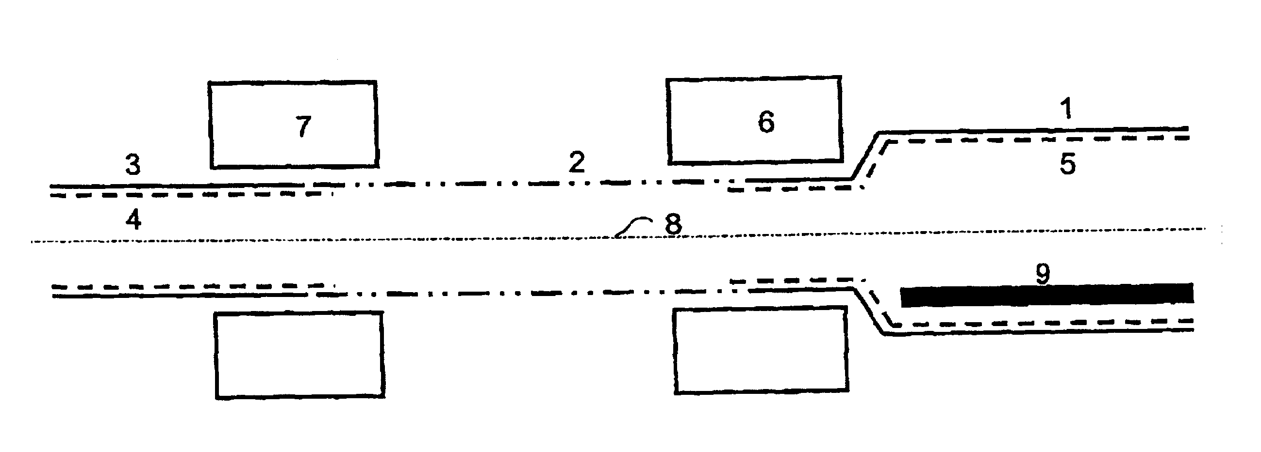
[0009] One or more of the above objects are accomplished when using such a device. More in particular, the low-quality quartz will accumulate in an insertion tube that thus is configured, which means that such quartz will be deposited on the interior of the insertion tube, which insertion tube will be removed upon completion of the deposition process. Consequently, no bubbles will form in the glass layers of the substrate tube during the contraction process that is carried out after the deposition process, whilst in addition the formation of cracks in the layers is prevented.
[0013] To prevent clogging of the passage in the substrate tube, it is desirable that the internal diameter of the discharge tube in the area outside the section between the two points of reversal is larger than the internal diameter of the substrate tube, with the transition from the diameter of the substrate tube to the diameter of the discharge tube taking place gradually.
[0015] In another special embodiment, the supply side is so configured that an insertion tube is disposed inside the supply tube, wherein, in a preferred embodiment, the external diameter and the shape of the insertion tube substantially correspond to the internal diameter and the shape of the supply tube, wherein it is furthermore preferable if the internal diameter of the supply tube is substantially the same as the internal diameter of the substrate tube. It is desirable that the insertion 1S tube at the supply side of the substrate tube extends further in the direction of the discharge side than does the supply tube. The inventors have found that stresses build up in glass layers in the transition area between deposition and no deposition, in particular if dopants are used. As a result of these inflow effects, glass layers may come loose from the interior of the substrate tube in the aforesaid transition area. By having the deposition take place in an insertion tube in said inflow area, the glass layers are prevented from coming loose, or such undesirable effects are at any rate prevented from extending inside the substrate tube.
[0017] When the present device is used, no crack formation will take place in the deposited layers either during the deposition process or after the deposition process, whilst in addition no bubble formation will take place during the contraction process. When the present device is used, a longer (in time) deposition process will moreover be possible, because the extent to which clogging may occur at the discharge side has been minimised. In addition to that the present inventors have found that no undesirable change will take place as regards the uniformity of the solid preform obtained after contraction, in particular at the supply side of the substrate tube. Using the present device, a substantially full utilisation of the glass material of the substrate tube of a high quality, viz. a maximum utilisation of the length of the substrate tube for drawing optical fibres therefrom, is possible therefore.

Problems solved by technology

The present inventors have found that such low-quality quartz may adversely affect the substrate tube, in particular as a result of the formation of gas bubbles at the supply side of the substrate tube upon contraction of the hollow substrate tube into a solid form.
In addition to that the present inventors have found that such low-quality quartz may come loose from the substrate tube during the contraction process, which may result in contamination or bubble formation elsewhere in the substrate tube.
Another negative aspect is that cracks may occur in the low-quality quartz region, which cracks may propagate in the direction of the centre of the substrate tube, which is undesirable.
The present inventors have furthermore found that the low-quality quartz may lead to clogging, as a result of which the pressure may rise to an undesirably high level during the deposition process, which has a negative effect on the deposition process in the substrate tube, which manifests itself in the form of a white colour in practice.
In practice the total length of the substrate tube will be longer than the portion of the substrate tube that wilt eventually be converted into a glass fibre by means of a drawing process, however, because the two ends of the substrate tube, where deposition takes place, may cause undesirable side effects, viz. deposition defects, contamination, bubble formation and the like.

Method used


Image

  • Device and method for manufacturing and optical preform
  • Device and method for manufacturing and optical preform

Examples


Embodiment Construction

[0020] The present invention will be explained hereinafter by means of an example, in which connection it should be noted, however, that the present invention is by no means limited to such a special example.

[0021] The figure schematically shows the device according to the present invention. A hollow substrate tube 2 is provided with glass-forming precursors (not shown), with the gas flow taking place from the left to the right, seen in the figure. To effect a deposition of such glass-forming precursors, a resonator 10 for generating a plasma is reciprocated along the length of the substrate tube 2, with the resonator for generating plasma reversing at the discharge side, at the position indicated at 6, and subsequently being moved back in the direction of the supply side along the length of the substrate tube 2, from where it returns to the discharge side again, with the point of reversal at the supply side being schematically indicated at 7. For the sake of completeness it should...


PUM

PropertyMeasurementUnit
Lengthaaaaaaaaaa
Diameteraaaaaaaaaa
Areaaaaaaaaaaa

Abstract

The present invention relates to a device for manufacturing an optical preform by means of an internal vapour deposition process, said device comprising an energy source and a substrate tube, which substrate tube comprises a supply side for supplying glass-forming precursors and a discharge side for discharging constituents that have rot been deposited on the interior of the substrate tube, said energy source being movable along the length of the substrate tube between a point of reversal at the supply side and a point of reversal at the discharge side.

Description

BACKGROUND OF THE INVENTION Field of the Invention [0001] The present invention relates to a device and a method for manufacturing an optical preform by means of an internal vapour deposition process, said device comprising an energy source and a substrate tube which substrate tube comprises a supply side for supplying glass-forming precursors and a discharge side for discharging constituents that have not been deposited on the interior of the substrate tube, said energy source being movable along the length of the substrate tube between a point of reversal at the supply side and a point of reversal at the discharge side. Background [0002] Such a device is known per se from Korean patent application No. 2003-774952. The device that is known therefrom is used for manufacturing an optical preform by means of an MCVD (Modified Chemical Vapour Deposition) process, wherein use is made of a discharge tube and an insertion tube, which discharge tube is attached to the substrate tube. The i...

Claims


Application Information

Patent Timeline
IPC IPC(8): B29D11/00C03B37/018G02B6/00
CPCC03B37/01846G02B6/00C03B37/00
Inventor VAN STRALEN, MATTHEUS JACOBUS NICOLAASSWARTS, MARTINUS JOHANNES MARINUS JOZEPHMILICEVIC, IGORKORSTEN, MARCO
Owner DRAKA COMTEQ BV
Learn More