Cup seal and master cylinder employing the same

a technology of master cylinder and seal, which is applied in the direction of rotary clutches, fluid couplings, brake systems, etc., can solve the problems of erratic sealing point of inner lip, inability to supply fluid quickly and securely, and inability to secure the supply of fluid to the fluid pressure chamber when the piston is withdrawn. , to achieve the effect of improving the property of supplying fluid, easy deflection and easy sucking

Inactive Publication Date: 2007-07-12
BOSCH CORP
View PDF3 Cites 5 Cited by
  • Summary
  • Abstract
  • Description
  • Claims
  • Application Information

AI Technical Summary

Benefits of technology

[0020] According to the cup seal of the present invention, the lip side fluid passage grooves are formed in the inner lip so that the hydraulic fluid flowed through the base side grooves when the supply of hydraulic fluid flows through the lip side fluid passage grooves, thereby further improving the property of supplying fluid of the cup seal.
[0021] Further according to the cup seal of the present invention, the inner lip is formed to be thicker than the outer lip, that is, the inner lip into which the slidable member is slidably inserted is thick so that the inner lip is endowed only with the sealing function, while the outer lip is thin so as to allow the outer lip to be easily deflected and allow the hydraulic fluid to be easily sucked so that the outer lip is endowed both with the sealing function and the pumping function. Therefore, the cup seal is prevented from being caught by the slidable member, thereby improving the durability of the cup seal. According to the cup seal of the invention as claimed in claim 4, the sealing function, the fluid supplying function, and fluid self-feeding function can be effectively exhibited with a simple structure without changing significantly the design of a conventional cup seal, just by forming grooves having a simple shape for allowing the flow of hydraulic fluid and designing the inner lip and the outer lip such that the inner lip is thicker than the outer lip.
[0022] According to the master cylinder of the present invention, in operation, the inner lip is pressed into close contact with the outer peripheral surface of the primary piston and the outer lip is pressed into close contact with the bottom wall of the concavity by the fluid pressure developed in the fluid pressure chamber, whereby reliable sealing action is obtained, thereby improving the sealing performance by the cup seal.
[0023] When negative pressure tends to be developed in the fluid pressure chamber during retraction of the piston according to cancellation of the pedaling operation, the hydraulic fluid of the reservoir can be supplied to the fluid pressure chamber through the base side grooves formed in...

Problems solved by technology

When the inner lip is formed to be thin, however, a problem that the inner lip enters in the relief port, i.e. is caught by the piston, is caused.
When the inner lip is provided with the tapered surface, however, there is a problem that rapid and secure supply of fluid to the fluid pressure chamber when the piston is retracted is impossible, that is, the property of supplying fluid should not be well.
Furthermore, since the inner lip has the tapered surface, there is also a ...

Method used


Image

  • Cup seal and master cylinder employing the same
  • Cup seal and master cylinder employing the same
  • Cup seal and master cylinder employing the same

Examples


Embodiment Construction

[0031] Hereinafter, embodiments of the present invention will be described with reference to the attached drawings.

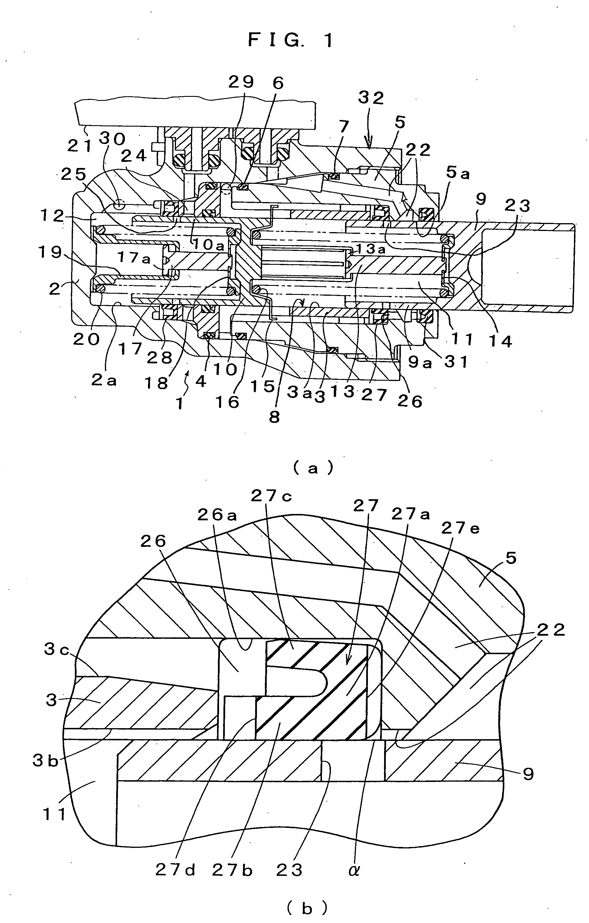
[0032] FIGS. 1(a), 1(b) show an example of plunger-type master cylinder to which an embodiment of the cup seal according to the present invention is adopted, wherein FIG. 1(a) is a longitudinal sectional view and FIG. 1(b) is a partially enlarged sectional view of FIG. 1(a). In the following description, the terms such as “front or fore” and “rear or back” refer to the left and the right, respectively, in the drawings.

[0033] As shown in FIGS. 1(a) and 1(b), the plunger-type master cylinder 1 is provided with s first cylinder member 2. In the first cylinder member 2, a sleeve 3 is fitted fluid-tightly to the inner surface of the first cylinder member 2 by a sealing member 4 and a second cylinder member 5 is fitted fluid-tightly to the inner surface of the first cylinder member 2 by sealing members 6, 7 and is threadably fixed to the first cylinder member 2. Therefore, ...


PUM


Abstract

In a cup seal of the present invention, an inner lip (27b) is pressed into close contact with a piston (9) and an outer lip (27c) is pressed into close contact with a bottom wall (26a) of a concavity (26) by fluid pressure developed in a fluid pressure chamber (11) when the piston (9) moves forward. Therefore, fluid pressure is sealed. When the piston (9) is retracted, the outer lip (27c) is deflected inwardly and is thus spaced apart from the bottom wall (26a) of the concavity (26). Hydraulic fluid of a reservoir is supplied to the fluid pressure chamber (11) through a first communication path (22), grooves (27e), and the space between the outer lip (27c) and the bottom wall (26a). As mentioned above, the inner lip (27b) has only the sealing function, while the outer lip (27c) has both the sealing function and the pumping function and ensures sufficient fluid supply by the grooves.

Description

BACKGROUND ART [0001] The present invention relates to technical field of a cup seal to be used in a master cylinder of a brake or a clutch of a vehicle such as an automobile, or the like and to a technical field of a plunger-type master cylinder employing the cup seal. [0002] Conventionally, a master cylinder for developing fluid pressure according to pedaling force on a brake pedal or a clutch pedal is used in a hydraulic brake system or a hydraulic clutch system for the purpose of actuating a brake or a clutch. As such a master cylinder, a plunger-type master cylinder is known from Japanese Unexamined Patent Publication No. 2003-194100, which comprises a cylinder body having a cylinder bore, a piston which is slidably inserted into the cylinder bore and defines a fluid pressure chamber, a communication path which is formed in the cylinder body and communicates with a reservoir, a relief port which is formed in the piston to allow communication between the communication path and t...

Claims


Application Information

Patent Timeline
IPC IPC(8): F15B7/00B60T11/16B60T11/232B60T11/236F16J15/16F16J15/18F16J15/3236
CPCF16J15/164B60T11/236B60T11/16F16J15/18F16J15/32
Inventor CHIBA, SHUSAKU
Owner BOSCH CORP
Why Eureka
Try Eureka