
Noncontact fever screening system

Inactive Publication Date: 2007-07-05
FRADEN JACOB
View PDF8 Cites 92 Cited by
  • Summary
  • Abstract
  • Description
  • Claims
  • Application Information

AI Technical Summary

Problems solved by technology

Development of the global mass transportation systems which quickly move people from one country to another increases a risk of spreading infectious diseases, such as SARS (severe acute respiratory syndrome).
If not controlled, this may cause a pandemic outbreak.
Even a very inefficient transportation system, such as by steamboats, allowed in 1918 a global spreading of viral infection which just within two weeks caused a flu pandemic that took millions of lives.
Most of dangerous infections, when progressing from the incubation to active phase, manifest in elevated body temperatures (fever).
The only infrared thermometers that do not touch the subject are non-medical optical thermometers having relatively wide angle of view of several degrees or larger and thus not accurate in fever detection.
1. A physical contact with a human subject (even when the protective covers are employed) may increase risk of spreading infection due to a cross-contamination.
2. A slow speed response—even the fastest thermometers of all (IR ear thermometers, e.g.) which have response times around 1 s, still require handling, the probe cover installation, subject preparation and data registration—totaling to at least 15 s per subject.
3. The infrared thermometers that measure temperature from a distance have poor accuracy due their nature—a poor spatial resolution, so they register an average temperature of the subject that makes fever detection highly inaccurate.
Use of a thermal imaging camera while generally attractive due to its numerous advantages, has several limitations, such as a need for the human data interpretation, thermal drifts, low temperature resolution, uncertainty in the subject skin emissivity, strong variations in temperature over the subject's face, effects of the ambient air temperature and many others.
These factors reduce effectiveness of the thermal imaging and make its use in the mass fever screening not only expensive, but also inefficient and unreliable.

Method used


Image

  • Noncontact fever screening system
  • Noncontact fever screening system
  • Noncontact fever screening system

Examples


Embodiment Construction

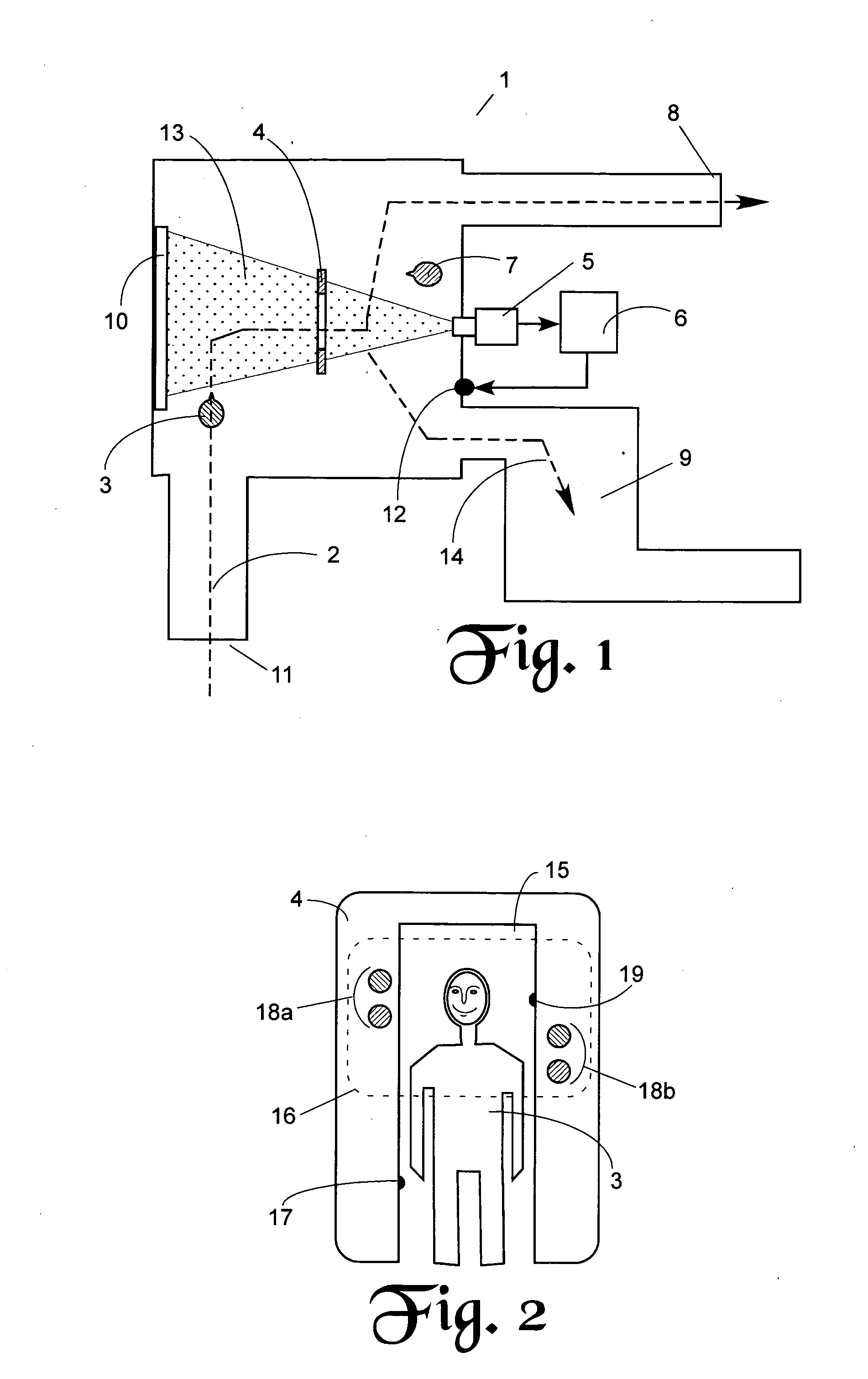
[0024]A typical arrangement of the fever screening at a port of entry may be as follows. In an airport, e.g., the test area is situated in a close proximity to an arrival gate. Before exiting from the airport, every passenger and crew member first must pass through the fever screening area 1 whose general layout plan is depicted in FIG. 1. The walking path 2 of a subject 3 leads from the entrance 11 through the target gate 4 and then to the exit 8. The target gate 4 is the place where a fever detection takes place. The detection is performed by the thermal imaging camera 5 and signal processing equipment 6. The equipment 6 is connected to an indicator, for example, an alarm 12 which is activated when fever is detected. The screening operator 7 supervises the procedure and directs the subject 3 either to exit 8 or to the secondary screening section 9 where the selected subjects who triggered the alarm 12, undergo the secondary testing with a conventional clinical thermometer. If feve...


PUM


Abstract

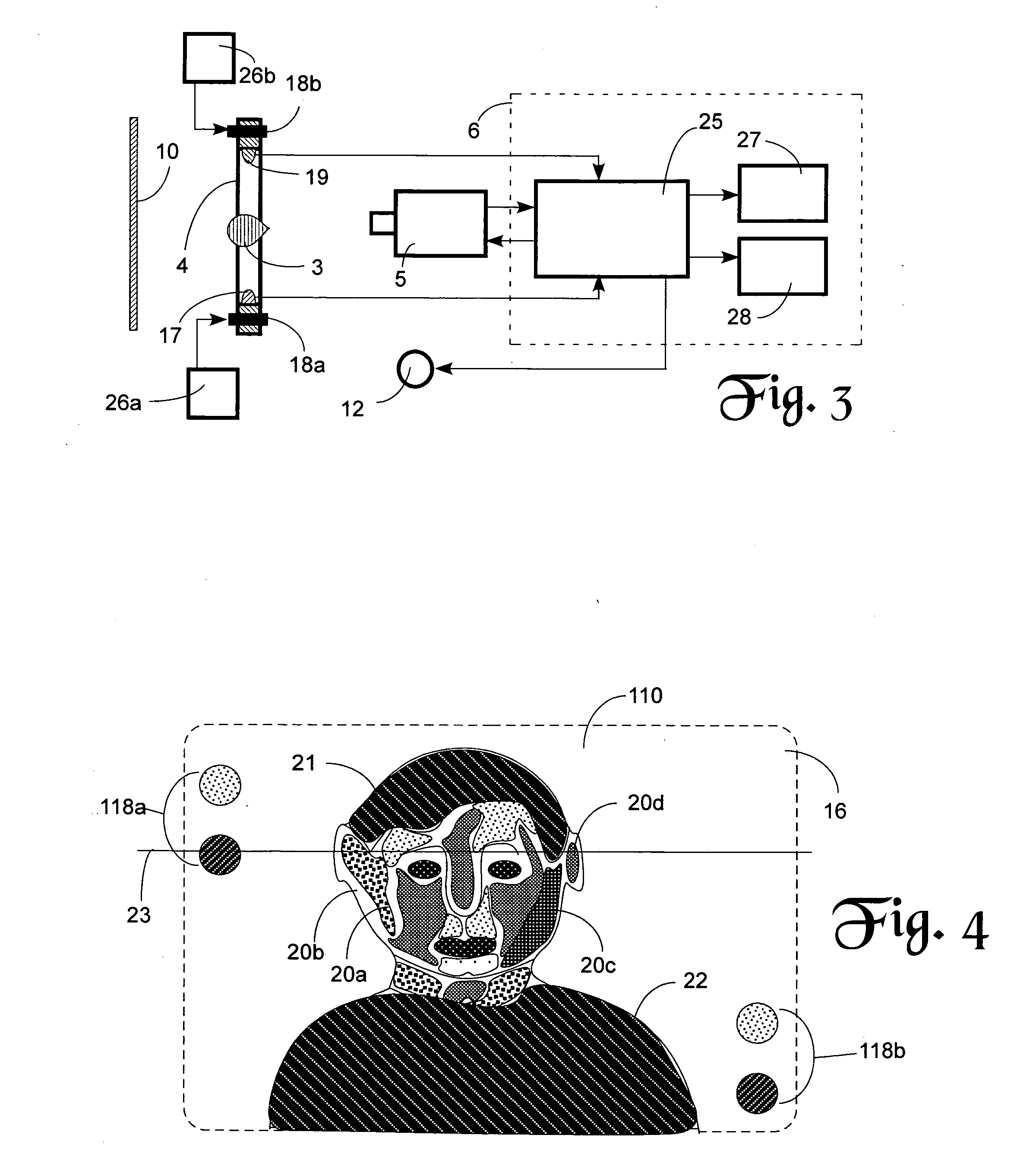
A system for fast noncontact screening for fever human subjects by means of a thermal imaging camera. The camera is combined with a target gate that incorporates the reference blackbody targets and position detectors to identify the temperature scale and size of a subject. A thermal imaging snapshot is controlled by the position detectors. An afebrile subject produces pixels of a thermal image that fit within the predetermined normal temperature range calibrated by the reference blackbody targets and having no pixels above that range. Exceeding that range by at least two adjacent pixels is an indication of fever that triggers the alarm.

Description

FIELD OF INVENTION[0001]This invention claims the benefit of a Provisional U.S. Patent Application No. 60 / 754,996 filed on Dec. 30, 2005. It relates to a medical thermal imaging. More particularly, it relates to devices for the automatic screening of people for fever by means of a thermal imaging device.DESCRIPTION OF PRIOR ART[0002]Development of the global mass transportation systems which quickly move people from one country to another increases a risk of spreading infectious diseases, such as SARS (severe acute respiratory syndrome). If not controlled, this may cause a pandemic outbreak. Even a very inefficient transportation system, such as by steamboats, allowed in 1918 a global spreading of viral infection which just within two weeks caused a flu pandemic that took millions of lives. An effective way to limit a risk of pandemic is by preventing the carriers of viral or bacterial infections (infected subjects) to move from place to place and contact other people. This requires...

Claims


Application Information

Patent Timeline
IPC IPC(8): G01J5/00
CPCA61B5/015G01J5/0022G01J2005/0077G01J5/522G01J5/0025G01J5/53
Inventor FRADEN, JACOB
Owner FRADEN JACOB
Learn More