
Bridge, computer system and method for initialization

a computer system and bridge technology, applied in the field of computer systems, can solve the problems of signal interference, waste and inconvenience, and increase the complexity of the circuit layout,

Inactive Publication Date: 2007-06-21
MITAC INT CORP
View PDF12 Cites 10 Cited by
  • Summary
  • Abstract
  • Description
  • Claims
  • Application Information

AI Technical Summary

Benefits of technology

[0011] In view of the problems and shortcomings of the prior art, the present invention provides a computer system and its bridge module, which can be used to maintain the communication between processor and chipset, processor and I / O controller or processor and sub-system, without having to install additional processors or change the framework of the computer system.

Problems solved by technology

However, for such a framework, when the motherboard used for double processors is only plugged on with one processor, then in addition to the problem of increased load, the related functions of a chipset connected to vacant processor socket, such as the various functions of PCI expansion card connected to the PCI bridge chip may not be utilized at all, thus resulting in tremendous waste and inconvenience.
However, the arrangement of such a predetermined cross-coupled framework will inevitably add to the complexity of the circuit layout.
For example, if bus termination operation has not been performed, then the continuously transmitted signals will be reflected back to the original transmitting device at the end of the bus since they have not been received by the idle processor, thus creating signal interference.
This phenomenon tends to become even more serious in high speed bus.
It is not a very satisfactory solution.
Moreover, in the multi-processor system such as an 8 processors system, the devoid of any of the processors would cause the termination of connections with other processors or the increase of transmission delay.
Thus, the afore-mentioned predetermined cross-coupled technology can not solve this problem due to the restriction of predetermined number of transmission channels of the respective processors.

Method used


Image

  • Bridge, computer system and method for initialization
  • Bridge, computer system and method for initialization
  • Bridge, computer system and method for initialization

Examples


Embodiment Construction

[0026] The purpose, construction, features, and functions of the invention can be appreciated and understood more thoroughly through the following detailed description with reference to the attached drawings.

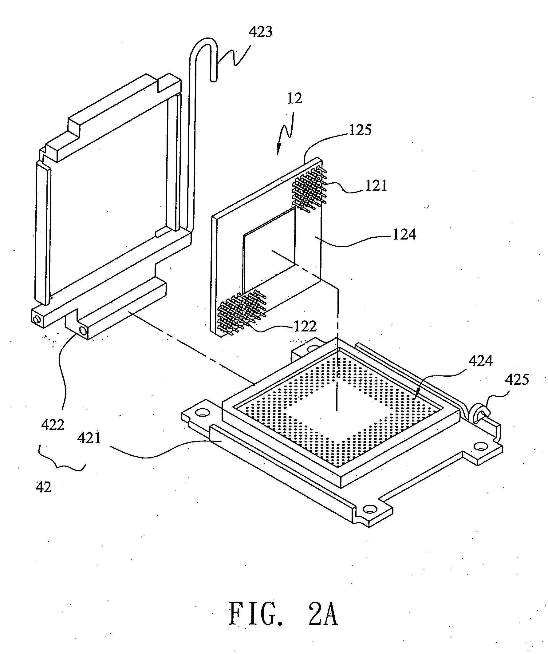
[0027] Before going into details of the system and method used for initializing the bridge module plugged onto the processor socket, the bridge module to be initialized is first described. For better understanding of the bridge module, the portions related to identifying the bridge module, and the adjustment portion of the initialization procedure for the computer system are omitted in FIGS. 1 to 4, so as not to obscure the essence of the bridge module.

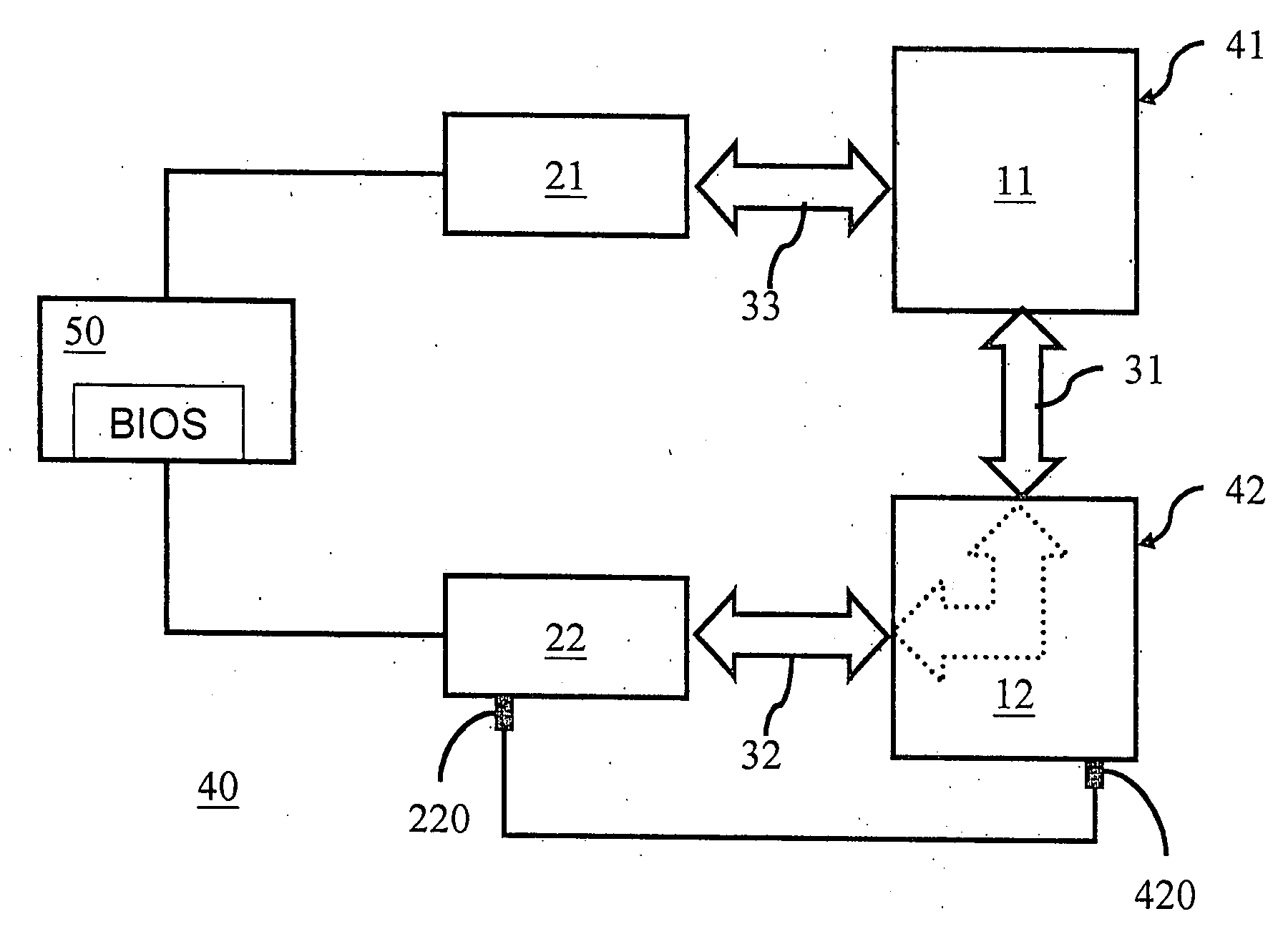
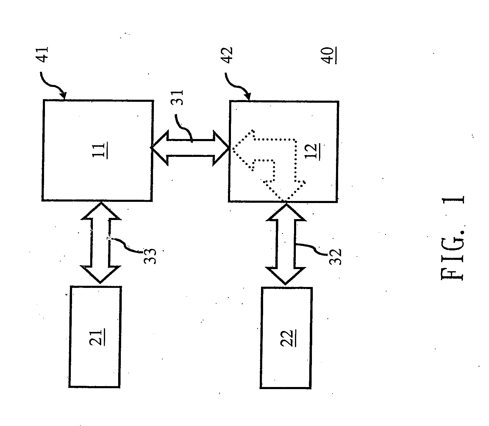
[0028] Refer to FIG. 1 for a schematic diagram of applying a bridge module to a dual processor computer system according to an embodiment of the present invention. As shown in FIG. 1, the dual processor system includes: a motherboard 40, a first bus 31, a second bus 32, a third bus 33, a processor 11, and a bridge module 12. A f...


PUM


Abstract

An indicator pin of an input / output controller is used to identifying whether a processor or a bridge is configured in a processor. When a predetermined voltage level of the indicator pin is confirmed, a base input / output system of the computer system renews a coherent / non-coherent HyperTransport link table. Then an initialization procedure is performed in accordance with the renewed coherent / non-coherent HyperTransport link table.

Description

BACKGROUND [0001] 1. Field of Invention [0002] The present invention relates to a computer system used in processing the electronic data, and in particular to a computer system having a bridge module plugged into the socket of a processor, thus connecting it in series with a Bus. [0003] 2. Related Art [0004] In a computer system, the most essential constituting portion is the motherboard, which is used to carry and support the various electronic components, among them the processor is the most important element, such as the central processing unit (CPU), which is responsible for the major task of various data operations, and thus be considered as the core of the entire computer system. In order to handle the increasingly complicated and sophisticated data processing, the capability of a single processor sometimes is not sufficient to cope with the requirement of operation, thus bringing about the emergence of the multi-processor system having two or more processors on the same mothe...

Claims


Application Information

Patent Timeline
IPC IPC(8): G06F13/36
CPCG06F13/4027G06F13/4068
Inventor YANG, SHAN-KAIDING, LEIZHAO, LI-JIAN
Owner MITAC INT CORP
Learn More