
System and Method for Generating Hydrogen Gas

Inactive Publication Date: 2007-06-21
CENESTRA
View PDF5 Cites 114 Cited by
  • Summary
  • Abstract
  • Description
  • Claims
  • Application Information

AI Technical Summary

Benefits of technology

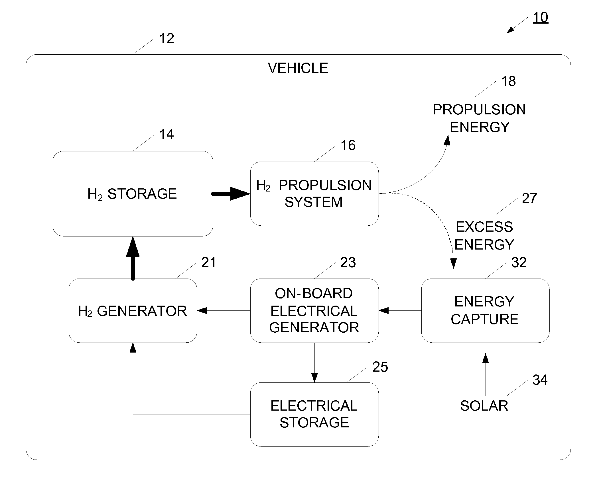
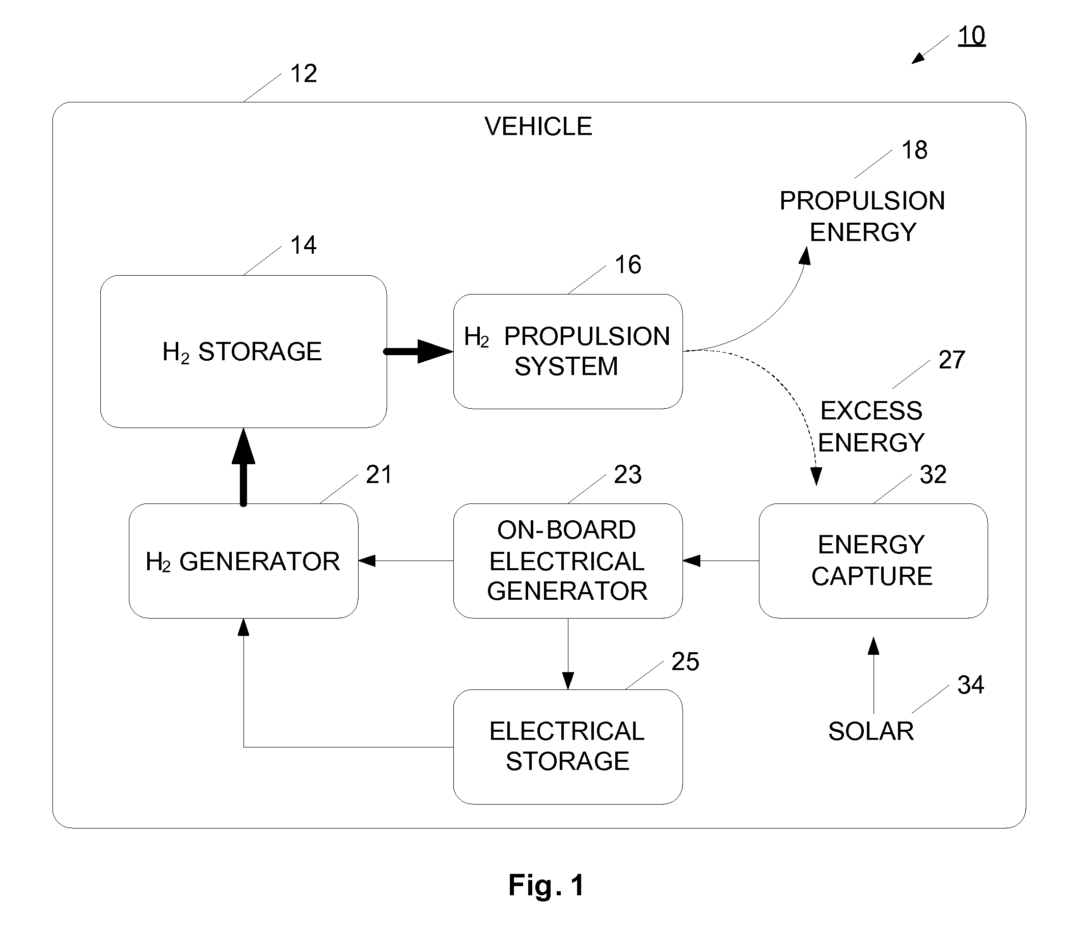
[0014] Advantageously, the present invention enables a hydrogen vehicle to operate on hydrogen gas with a reduced dependency on refueling. More particularly, the present invention enables the vehicle to utilize renewable sources of energy or regenerative energy for generating hydrogen gas for consumption in the vehicle's propulsion system. In some cases, both regenerative and renewable generation processes may be used. By enabling the use of hydrogen vehicles with reduced dependence of on refueling stations, the use and adoption of hydrogen vehicle systems may be accelerated. In this way, the use of carbon-based fuels, the emission of greenhouse gases, and dependency on unstable sources of energy may all be reduced.

Problems solved by technology

Unfortunately, hydrogen vehicles typically have a shorter range than a comparable carbon-fuel vehicle, so may require more refueling stations as compared to regular gas or diesel vehicles.
The new infrastructure to support hydrogen distribution represents a massive construction undertaking, will take years to build-out, and has an associated staggering cost.
However, until the hydrogen refueling issue is addressed, hydrogen-powered vehicles will not gain widespread use.
Across the nation there are a very limited number of filling stations where hydrogen may be purchased for drive up vehicles.
With so few hydrogen stations available, any user of a hydrogen vehicle has very limited range and destination options.
However, no practical way is known to generate hydrogen on-site for individual and commercial needs, exclusively by renewable energy sources, with no fossil fuel consumption or pollution.
The problems of previous efforts of producing hydrogen include high capital expenditures, fossil fuel consumption, pollution, low production, low efficiency, non-durable equipment, long distance energy transmission, and they do not make distributed energy on-site.

Method used


Image

  • System and Method for Generating Hydrogen Gas
  • System and Method for Generating Hydrogen Gas
  • System and Method for Generating Hydrogen Gas

Examples


Embodiment Construction

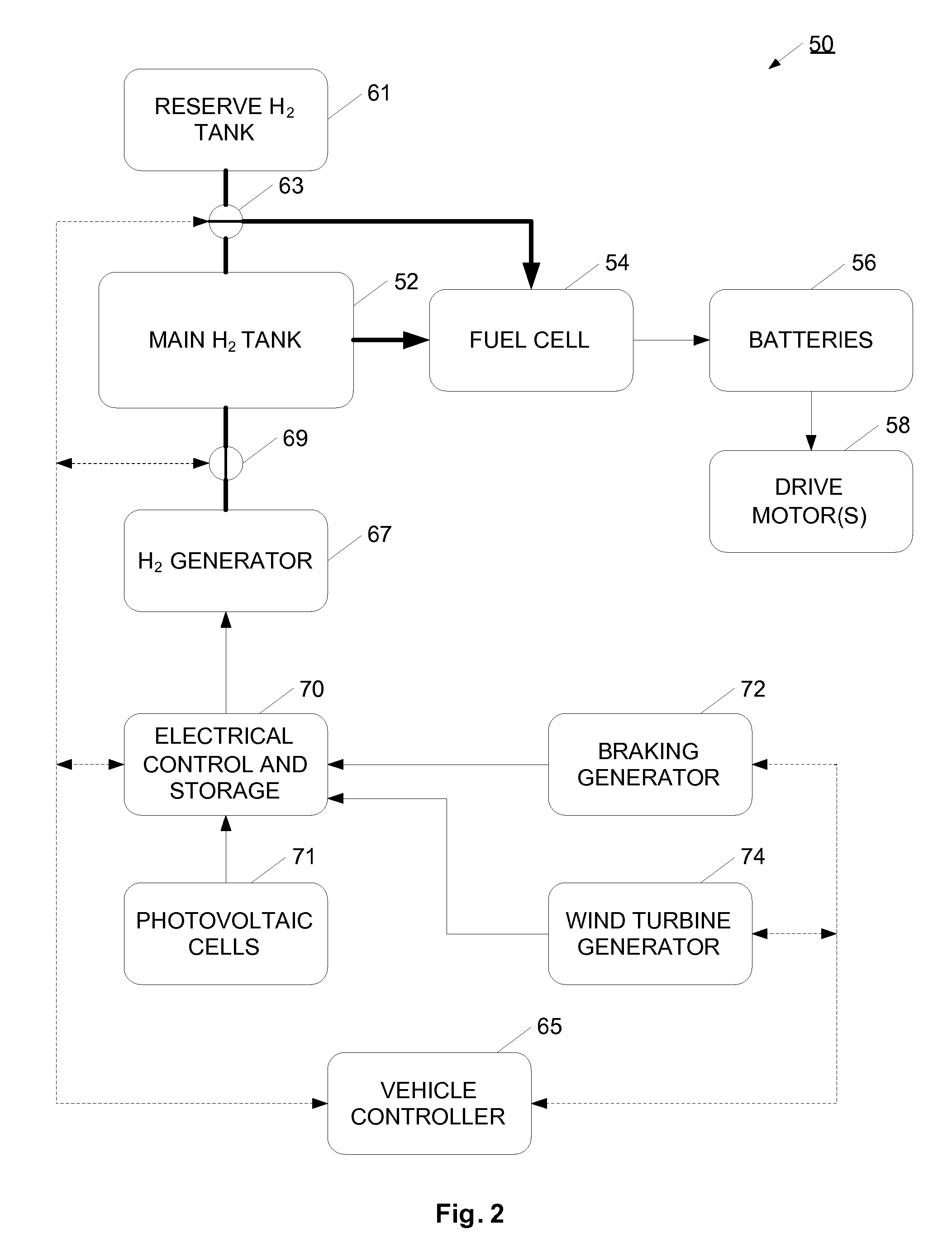
[0030] An active system and method is described for generating hydrogen gas on a motor vehicle itself, to be used as motive energy for vehicles. The system may employ multiple sources of on-board kinetic and renewable energy for onboard generation. The methods may include 1) capture of kinetic energy from the vehicle regenerative braking wheel system, 2) using air flow of the moving vehicle against fan blades on electrical generators as additional regenerative braking; 3) on-board generation using solar photovoltaic cells. The high peak electrical output generating methods such as braking, are used to generate electricity to be stored in electricity storage including batteries, capacitors, or spinning fly wheel, so that such electricity may be controlled and directed into an on-board low voltage direct photoelectrochemical hydrogen generator to disassociate water into hydrogen and oxygen. These onboard vehicle kinetic or renewable energy sources provide electrical current in a suita...


PUM

PropertyMeasurementUnit
Pressureaaaaaaaaaa
Pressureaaaaaaaaaa
Poweraaaaaaaaaa

Abstract

A hydrogen gas generation system is provided for use in a mobile vehicle. The mobile vehicle may be for example, a car or truck or other vehicle such as a balloon, dirigible, airship, ship, or boat. The vehicle has an on-board hydrogen generator for generating hydrogen gas, preferably using an electrolysis process. The hydrogen produced by the electrolysis process is stored in an on-board hydrogen storage tank. Hydrogen from the storage tank is flowed into a vehicle propulsion system where the hydrogen gas is consumed to provide power to propel the vehicle. An on-board electrical generation system provides at least some of the electricity for the electrolysis process. In one example, the vehicle has an on-board electrical generator for providing electricity for the electrolysis process. The on-board electric generation system may be, for example, a solar photovoltaic cell system, a wind turbine generator system, or a regenerative braking generator, for example. Depending on the particular electrical generation process or processes used, the vehicle may generate hydrogen gas when moving, when coasting or braking, or when long-term parked.

Description

RELATED APPLICATIONS [0001] This application claims priority to U.S. patent application No. 60 / 751,903, filed Dec. 21, 2005, and entitled “System and Method for Portable Onboard Vehicle Hydrogen Gas Generation Using Vehicle Kinetic Energy and Renewable Energy”; and is related to U.S. patent application Ser. No. 10 / 785,234, filed Feb. 24, 2004, and entitled “System and Method for Generating Hydrogen Gas Using Renewable Energy”; both of which are incorporated herein in their entirety.BACKGROUND [0002] 1. Field [0003] The field of the present invention is hydrogen generation. More particularly, the present invention relates to the generation of a hydrogen gas for mobile, vehicle, or portable applications. [0004] 2. Discussion of Prior Art [0005] Hydrogen gas shows great promise as a fuel for powering mobile vehicles such as cars and trucks. Hydrogen burns cleanly, and may be produced using renewable energy sources. Accordingly, it has the potential for reducing greenhouse gas emissions...

Claims


Application Information

Patent Timeline
IPC IPC(8): C25B9/00B60L11/18H01M8/18
CPCB60L8/00B60L11/1881B60L11/1892C25B1/003C25B1/04H01M8/0606H01M16/003H01M2250/20Y02E60/366Y02E70/10Y02T10/7083Y02T90/32Y02T90/34Y02E60/50B60L58/30B60L58/33Y02E60/36Y02T10/7072Y02T90/40C25B1/55
Inventor OAKES, THOMAS W.OAKES, ROBERT E.
Owner CENESTRA
Learn More