Fuel cell, disassembly method thereof, and separators used therein

a technology of separators and fuel cells, which is applied in the direction of cell components, cell component details, manufacturing tools, etc., can solve the problems of insufficient movement of linear members, failure to remove sealing members, and damage to linear members, so as to achieve easy and accurate positioning and easy breakage

Active Publication Date: 2007-06-14
TOYOTA JIDOSHA KK
View PDF1 Cites 24 Cited by
  • Summary
  • Abstract
  • Description
  • Claims
  • Application Information

AI Technical Summary

Benefits of technology

[0008] In the fuel cell of the invention, it is preferable that the breaking guide is used to break at least one of the separators at a position outside the electrodes but inside the sealing member. This arrangement enables the separator to be broken at the position outside the electrodes but inside the sealing member, while hardly damaging the electrodes of the electrode assembly, in the process of disassembling the fuel cell. The breaking guide may be formed at or in a neighborhood of a position of the sealing member on at least one of the separators. Also, the breaking guide may be formed in a thin-wall section formed on at least one of the separators.
[0040] In the fuel cell of the invention, the electrode assembly may be received in an inner space of an outer frame member. The outer frame member may be combined or integrated with one of the separators to form a container, where an opening of the container is closed by the other of the separators as a cover. In assembly of a fuel cell, this structure ensures easy and accurate positioning of the electrode assembly relative to the separator.

Problems solved by technology

In the structure of this prior art fuel cell, however, when the linear-member is tightly stuck to the sealing member, the pulling action of the linear member outward may not move the linear member sufficiently or may destroy the linear member.
The sealing member may thus not be peeled off successfully.
This structure accordingly does not ensure effective and efficient disassembly of the fuel cell.
This structure also requires the linear member between the sealing member and the separator and thus undesirably increases the total number of required elements.

Method used


Image

  • Fuel cell, disassembly method thereof, and separators used therein
  • Fuel cell, disassembly method thereof, and separators used therein
  • Fuel cell, disassembly method thereof, and separators used therein

Examples


first embodiment

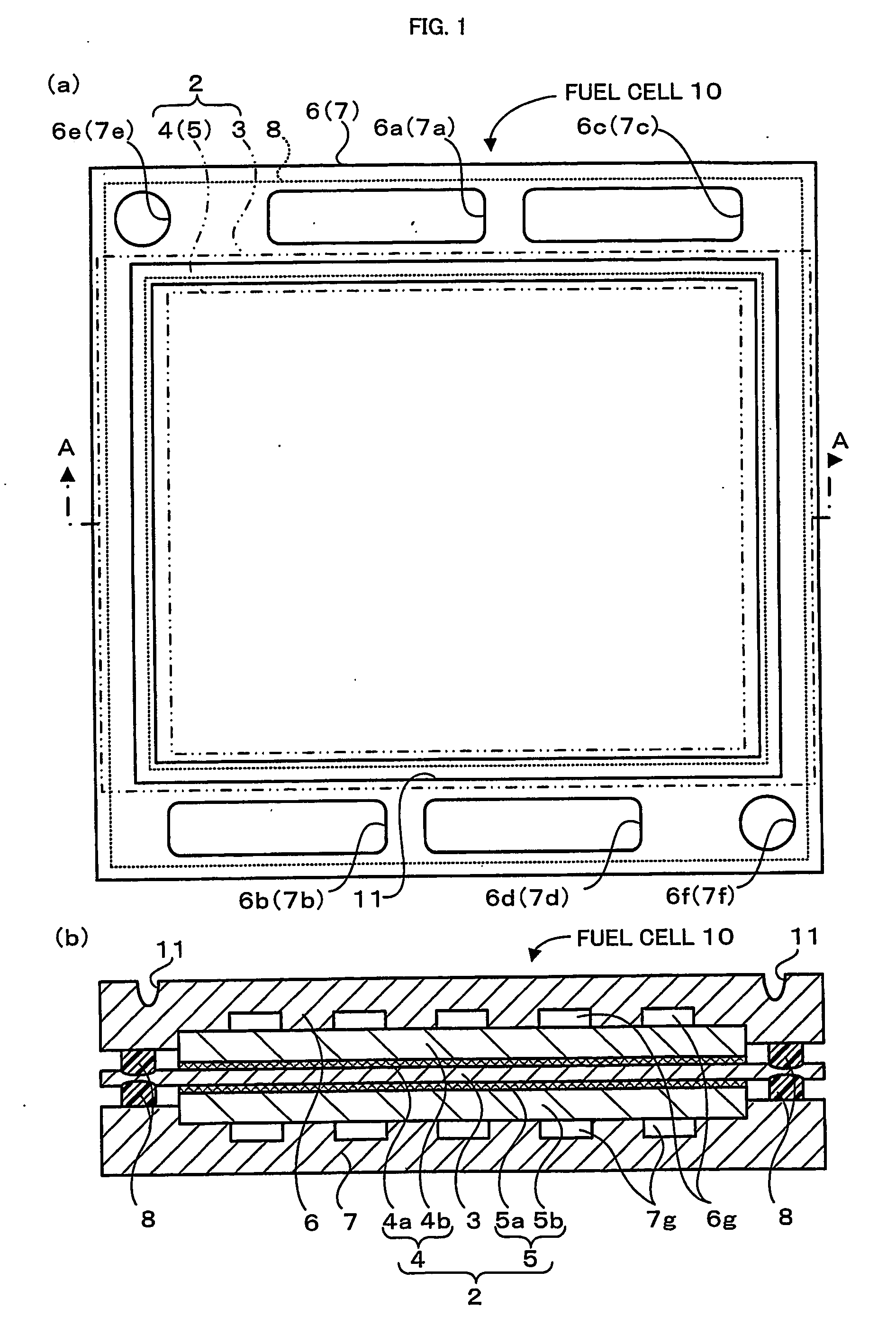
[0071]FIG. 1 schematically illustrates the structure of a fuel cell 10 in a first embodiment of the invention. FIG. 1(a) is a plan view, and FIG. 1(b) is a sectional view taken on a line A-A in FIG. 1(a).

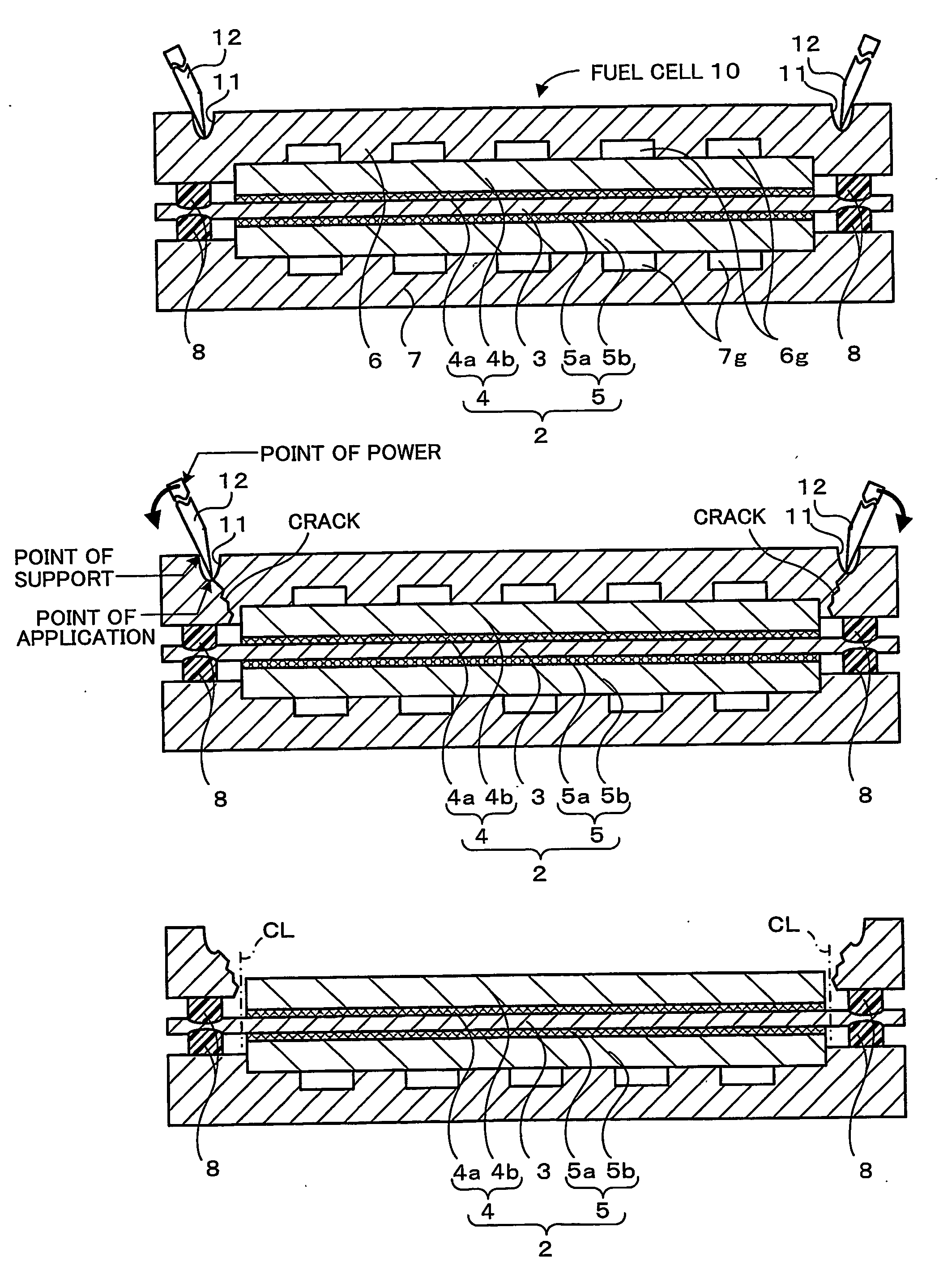
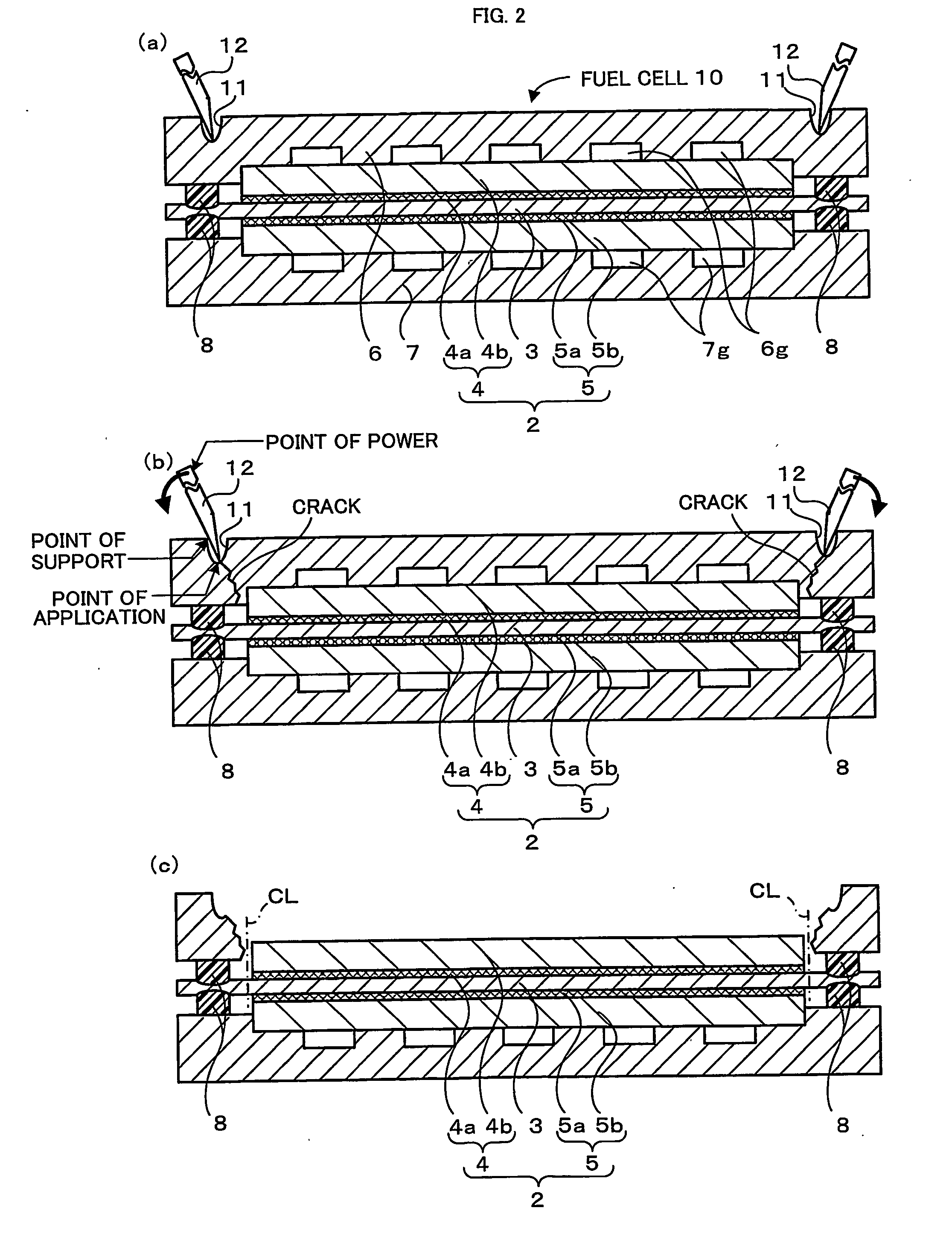
[0072] The fuel cell 10 of this embodiment is a polymer electrolyte fuel cell and includes, as main constituents, a membrane electrode assembly (hereafter referred to as MEA) 2 having an electrolyte membrane 3 interposed between a pair of electrodes 4 and 5, a pair of separators 6 and 7 arranged across the MEA 2, sealing members 8 located to surround the outer circumference of the MEA 2, and a recess 11 used as a breaking guide for breakage of one of the separators 6. The fuel cell 10 is a unit cell having an electromotive force in a range of about 0.6 to 0.8 V. A large number of the fuel cells 10 are tightly laid one upon another to form a direct current power source of several hundred volts as a power supply of, for example, a drive motor of the vehicle.

[0073] The MEA 2 has the ...

second embodiment

[0087]FIG. 10 schematically illustrates the structure of a fuel cell 20 in a second embodiment of the invention. FIG. 10(a) is a plan view, and FIG. 10(b) is a sectional view taken on a line C-C of FIG. 10(a).

[0088] The fuel cell 20 of this embodiment is a polymer electrolyte fuel cell and includes, as main constituents, an MEA 2 having an electrolyte membrane 3 interposed between a pair of electrodes 4 and 5, a pair of separators 6 and 7 arranged across the MEA 2, sealing members 8 located to surround the outer circumference of the MEA 2, and breaking guides 21 and 22 used for breakage of both the separators 6 and 7. The structures of the MEA 2, the separators 6 and 7, and the sealing members 8 are identical with those of the first embodiment and are thus not specifically described here. The like elements to those of the first embodiment are expressed by the like numerals and symbols.

[0089] The breaking guides 21 and 22 have recesses 21a and 22a formed on the other planes of the ...

third embodiment

[0096]FIG. 14 is a sectional view schematically illustrating the structure of a fuel cell 30 in a third embodiment of the invention. Like the sectional view of FIG. 1(b) in the first embodiment, this sectional view shows a cross section of the fuel cell cut in the direction of depth.

[0097] The fuel cell 30 of this embodiment is a polymer electrolyte fuel cell and includes, as main constituents, an MEA 2 having an electrolyte membrane 3 interposed between a pair of electrodes 4 and 5, a pair of separators 6 and 7 arranged across the MEA 2, sealing members 8 located to surround the outer circumference of the MEA 2, and breaking guides 31 used for breakage of both the separators 6 and 7. The structures of the MEA 2, the separators 6 and 7, and-the sealing members 8 are identical with those of the first embodiment and are thus not specifically described here. The like elements to those of the first embodiment are expressed by the like numerals and symbols.

[0098] The breaking guides 31...


PUM

PropertyMeasurementUnit
vertex angleaaaaaaaaaa
angleaaaaaaaaaa
electromotive forceaaaaaaaaaa

Abstract

A disassembly procedure of a fuel cell 10 first provides a cracking tool 12 having a sloped edge and places the sloped edge of the cracking tool 12 on a bottom of a recess 11. The disassembly procedure subsequently sets the bottom of the recess 11 where the sloped edge of the cracking tool 12 is placed, as a point of application, an opening edge of the recess 11 where a flat side of the cracking tool 12 is placed, as a point of support, and a base end of the cracking tool 12 where a force is applied, as a point of power, and applies an external force to the point of application by the principle of leverage. A crack starts from the point of application in a separator 6. The crack goes from the point of application toward a position outside electrodes 4 and 5 of an MEA (membrane electrode assembly) 2 but inside sealing members 8. The procedure then removes the broken separator 6 to expose the MEA 2 outside and cuts off an electrolyte membrane 3 along a cut line CL outside the electrodes 4 and 5 but inside the sealing members 8.

Description

FIELD OF THE INVENTION [0001] The present invention relates to a fuel cell, a disassembly method of the fuel cell, and separators used in the fuel cell. BACKGROUND ART [0002] A fuel cell of a known structure includes: an electrode assembly that has an electrolyte interposed between a pair of electrodes; a pair of separators that are arranged across the electrode assembly, where one of the separators facing one of the electrodes has an oxidizing gas conduit, while the other of the separators facing the other of the electrodes has a fuel gas conduit; and a sealing member that is formed along periphery of the electrode assembly in a gap between the pair of separators. In the fuel cell of this known structure, a supply of hydrogen is fed as a fuel gas to the fuel gas conduit, whereas a supply of the air is fed as an oxidizing gas to the oxidizing gas conduit. Hydrogen is separated into proton and electron at one of the electrodes (anode) facing the fuel gas conduit. The proton passes th...

Claims


Application Information

Patent Timeline
Patent Type & Authority Applications(United States)
IPC IPC(8): H01M8/02H01M2/08B23P19/00H01M8/00H01M8/10H01M8/24
CPCH01M8/00H01M8/008H01M8/0206Y10T29/49815H01M8/0267H01M8/241Y02E60/50H01M8/0247Y02W30/84H01M8/2483H01M8/0263H01M8/02H01M8/24H01M8/0271
Inventor TAKASE, HIRONARITSUGANE, TAKAHIDEKIKUCHI, YOSHIAKISUZUKI, HIROSHI
Owner TOYOTA JIDOSHA KK
Why Eureka
Try Eureka