
Field repairable high temperature smooth wear coating

a high temperature, wear-reparable technology, applied in the direction of machines/engines, mechanical equipment, light and heating equipment, etc., can solve the problems of high temperature durability of engine components, increased heat transmission, and insufficient mechanical properties, etc., to achieve improved heat rejection, low roughness finish, and improved heat rejection

Active Publication Date: 2007-06-14
GENERAL ELECTRIC CO
View PDF19 Cites 26 Cited by
  • Summary
  • Abstract
  • Description
  • Claims
  • Application Information

AI Technical Summary

Benefits of technology

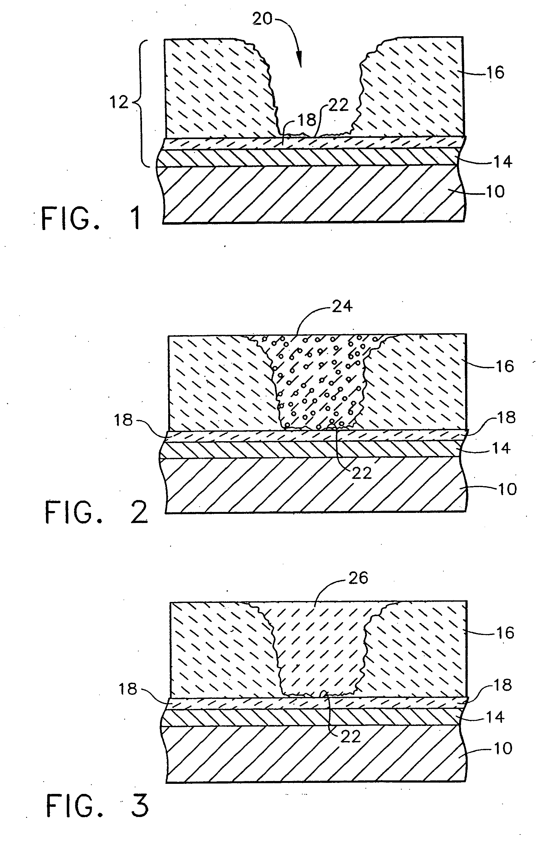
[0011] The present invention provides a chemical composition and method for repairing a thermal barrier coating on a component that has suffered due to spallation, fatigue, stress damage, poor coating processes, mechanical damage, or wear of the thermal barrier coating. The use of the methods and compositions of the present invention is particularly applicable for in-field repair of TBC coatings having spallation damage with a spall damage depth of between about 1 to about 50 mils (0.001 inch to 0.050 inch). For spalls having a depth of over 20 mils and approaching 50 mils, the composition of the present invention can be provided using a lower weight percentage of solvent, yielding putty-like properties to allow application of the composition using a blade or putty knife and to permit working and smoothing before drying.
[0012] The composition demonstrates thixotropic properties as a result of its selected components, and particularly the inclusion of at least one nano-sized ceramic material, such as fine or fumed ceramic material. The amount of nano-sized ceramic material such as alumina (Al2O3), titanium dioxide (TiO2), calcium oxide (CaO), magnesium oxide (MgO), or silicone dioxide (SiO2) is provided so as to impart thixotropic properties to the coating composition. The thixotropic properties are very important in allowing the coating to be applied in a non-controlled environment such as an on-wing turbine engine assembly. Even though the coating dries relatively quickly depending upon solvent selection and solvent content, time for polymerization and other stabilizing chemical and physical interactions can be 8 hours or longer. The thixotropic nature of the coating composition allows it to be applied to a surface, regardless of surface orientation, by a variety of processes without running, slumping or sagging while it dries, and further allows the coating to be worked as necessary. As used herein, the term thixotropic refers to a property of a material composition that enables it to flow when subjected to a mechanical force such as a shear stress or when agitated and return to a gel-like form when the mechanical force is removed. This definition is consistent with the definition of thixotropy as set forth in Hawley's Condensed Chemical Dictionary (Thirteenth Edition) and the Encyclopedia Britannica. This property allows the coating to be applied in a production or field repair environment to damaged surfaces having complex geometries, including but not limited to spalled areas of TBC coated components such as turbine blades and shrouds, without exposing the undamaged component surfaces underlying or adjacent to the damaged surfaces to slumping, running or dripping of the coating. These important thixotropic properties allow the coating to be applied to a surface by any one of a number of processes such as spraying, spackling, dipping, brushing etc. The applied coating will not flow due to the effects of gravity such as by slumping, running, or dripping after application. However, the coating will flow if it is subjected to a mechanical shear stress, allowing it to be worked, if so desired. Thus, during the early stages of the drying period the coating can be worked if necessary. Of course, the ability to work the coating will be gradually diminished during the drying period, wherein the solvent evaporates to form a coating including binder particles having polymeric bonds therebetween. The drying period is dependent on the evaporation of solvent and drying and the resulting formation of polymeric bonds or “curing” of the binder, up until drying is complete. These properties allow the coating to overcome problems of dripping and running experienced with other coatings, which problems can leave portions of the substrate uncoated.

Problems solved by technology

However, as operating temperatures increase, the high temperature durability of the components of the engine must correspondingly increase.
Nonetheless, when used to form components of the turbine, combustor and augmentor sections of a gas turbine engine, such alloys alone are often susceptible to damage by oxidation and hot corrosion attack and may not retain adequate mechanical properties.
Such TBC coatings have a relatively rough surface and do not provide adequate heat energy reflection for certain applications.
Accordingly, such coatings and methods cannot be effectively utilized in field repairs.
The latter requirement is particularly demanding due to the different coefficients of thermal expansion between ceramic topcoat materials and the superalloy substrates they protect.
The service life of a TBC system is typically limited by a spallation event brought on by thermal fatigue and stress, coating defects, mechanical damage, wear, and the like.
Accordingly, a significant challenge of TBC systems has been to obtain a more adherent ceramic layer that is less susceptible to spalling when subjected to thermal cycling.
Though significant advances have been made, there is the inevitable requirement to repair components whose thermal barrier coatings have spalled.
However, grit blasting is a slow, labor-intensive process and erodes the surface beneath the coating.
With repetitive use, the grit blasting process eventually destroys the component.
The use of an alkaline solution to remove a thermal barrier coating is also less than ideal, since the process requires the use of an autoclave operating at high temperatures and pressures.
Consequently, conventional repair methods are labor-intensive and expensive, and can be difficult to perform on components with complex geometries, such as airfoils and shrouds.
Moreover, existing sprayable TBC materials require some type of post drying or firing in order to be stabilized prior to high temperature use, and therefore are ineffective for in-situ field repairs.
Tape materials require an autoclave to apply, and are thus not feasible for in-situ repairs.
While plasma sprayed materials do not all require post-deposition heating, such materials have much rougher finishes, and cannot be applied in the field for in-situ repairs without spraying powder throughout the rest of the engine (which requires a major cleaning step prior to subsequent engine operation).
In the case of aircraft turbine engines and large power generation turbines, removing the turbine from service for repairs results in significant costs in terms of labor and downtime.
For these reasons, removing components having TBCs that have suffered only localized spallation is not economically desirable.
If the decision is to continue operation, the spalled component must typically be scrapped at the end of operation because of the thermal damage inflicted while operating the component without complete TBC coverage.
Currently, there is no known way at present to replace this smoothing layer having a very smooth finish on damaged TBC.

Method used


Image

  • Field repairable high temperature smooth wear coating

Examples


example 1

[0038]

Material Based on WeightGrams / WeightPercentagePercentDenatured Alcohol18.0 [5.39%]SM8 alumina37.6 [11.26%]A14 (−325 mesh) alumina51.6 [15.45%]Silicone binder (SR350)31.6 [9.46%]T-64 (−100 mesh) alumina143.1 plus 51.6[58.31%]Dibutyltin Dilaurate or Di-n-.2-.4 [0.001 toButylbis (2,4-0.1%]pentanedionate)tin

example 2

[0039]

Material Based on WeightPercentage]Weight %Denatured Alcohol or Acetone5.4SM8 alumina11.3A14 (−325 mesh) alumina30.6Silicone binder (SR3509.5T-64 (−100 mesh) alumina42.9Dibutyltin Dilaurate or Di-n-0.1Butylbis (2,4-pentanedionate)tin

example 3

[0040]

Material Based on WeightGrams / WeightPercentagePercentDenatured Alcohol 1-35% (balance)SM8 alumina 0-35%A14 (−325 mesh) alumina 0-35%Silicone binder (SR350) 3-45%T-64 (−100 mesh) alumina20-70%Accelerant0.01 to 15Dispersant0.01 to 5

[0041] The above are exemplary, and are not limiting. Other combinations and variations of ingredients and amounts are within the scope of the invention.

[0042] In order to prepare the chemical composition 24 the ceramic powder and nano-sized ceramic material(s) are combined with the binder and solvent in an amount sufficient to preferably form a paste-like mixture. A ceramic to binder ratio of about 8 to 1 is generally preferred, such as when using the above-noted combinations. Although a paste-like mixture is preferred, additional solvent can be provided to yield a more fluid mixture if spraying application methods are to be used.

[0043] Preferred binders include silicone resins manufactured by GE Silicones under the names SR350 and SR355, and class...


PUM

PropertyMeasurementUnit
Temperatureaaaaaaaaaa
Lengthaaaaaaaaaa
Lengthaaaaaaaaaa

Abstract

A chemical composition and method for repairing a thermal barrier coating on a component designed for use in a hostile thermal environment, such as turbine, combustor and augmentor components of a gas turbine engine. The method repairs a thermal barrier coating on a component that has suffered localized damage to the thermal barrier coating. After cleaning the surface area of the component exposed by the localized spallation, a paste-like mixture of a ceramic composition comprising ceramic powders and nano-sized ceramic materials in a binder, further including an accelerant, is applied to the surface area of the component, and is optionally smoothed using mechanical means. The composition is then allowed to dry and cure to form a dried coating having polymeric characteristics. Upon subsequent heating, the dried coating reacts to produce a glassy ceramic repair coating. Due to the thixotropic properties of the coating composition upon application to a component, the repair method can be performed in-situ while the component remains installed in its operating environment.

Description

CROSS-REFERENCE TO RELATED APPLICATIONS [0001] This application is a Continuation in Part of U.S. patent application Ser. No. 10 / 819,856, filed Apr. 7, 2004.FIELD OF THE INVENTION [0002] This invention relates to thermal barrier coatings for components exposed to high temperatures, such as the hostile thermal environment of a gas turbine engine. More particularly, this invention is directed to a composition and method for repairing a thermal barrier coating that has suffered localized spallation due to thermal fatigue and stress, poor coating processes, coating defects, localized damage, impact damage and other mechanical damage, or defective coating areas on new or used parts. BACKGROUND OF THE INVENTION [0003] Higher operating temperatures for gas turbine engines are continuously sought in order to increase their efficiency. However, as operating temperatures increase, the high temperature durability of the components of the engine must correspondingly increase. Significant advanc...

Claims


Application Information

Patent Timeline
IPC IPC(8): B05D3/00B05D5/00B05D3/12B05D3/02
CPCC09D1/00C23C24/08C23C24/082C23C26/00F01D5/288F23R2900/00019Y02T50/67Y02T50/671F05D2230/90F05D2230/80Y02T50/60
Inventor SKOOG, ANDREW JAYMURPHY, JANE ANNSTOWELL, WILLIAM RANDOLPHCALDWELL, DAVID E.
Owner GENERAL ELECTRIC CO
Learn More