
Computer chassis for improved airflow and heat transfer from computer system components

a computer system and chassis technology, applied in the direction of electrical apparatus casings/cabinets/drawers, cooling/ventilation/heating modifications, instruments, etc., can solve the problems of reducing the reliability and performance of most components, reducing the potential heat dissipation of each component, and creating significant reliability and performance bottlenecks for system builders, so as to reduce the occurrence of trapped air pockets, improve the airflow through the computer chassis, and reduce the effect of cooling components o

Active Publication Date: 2007-06-14
NVIDIA CORP
View PDF28 Cites 44 Cited by
  • Summary
  • Abstract
  • Description
  • Claims
  • Application Information

AI Technical Summary

Benefits of technology

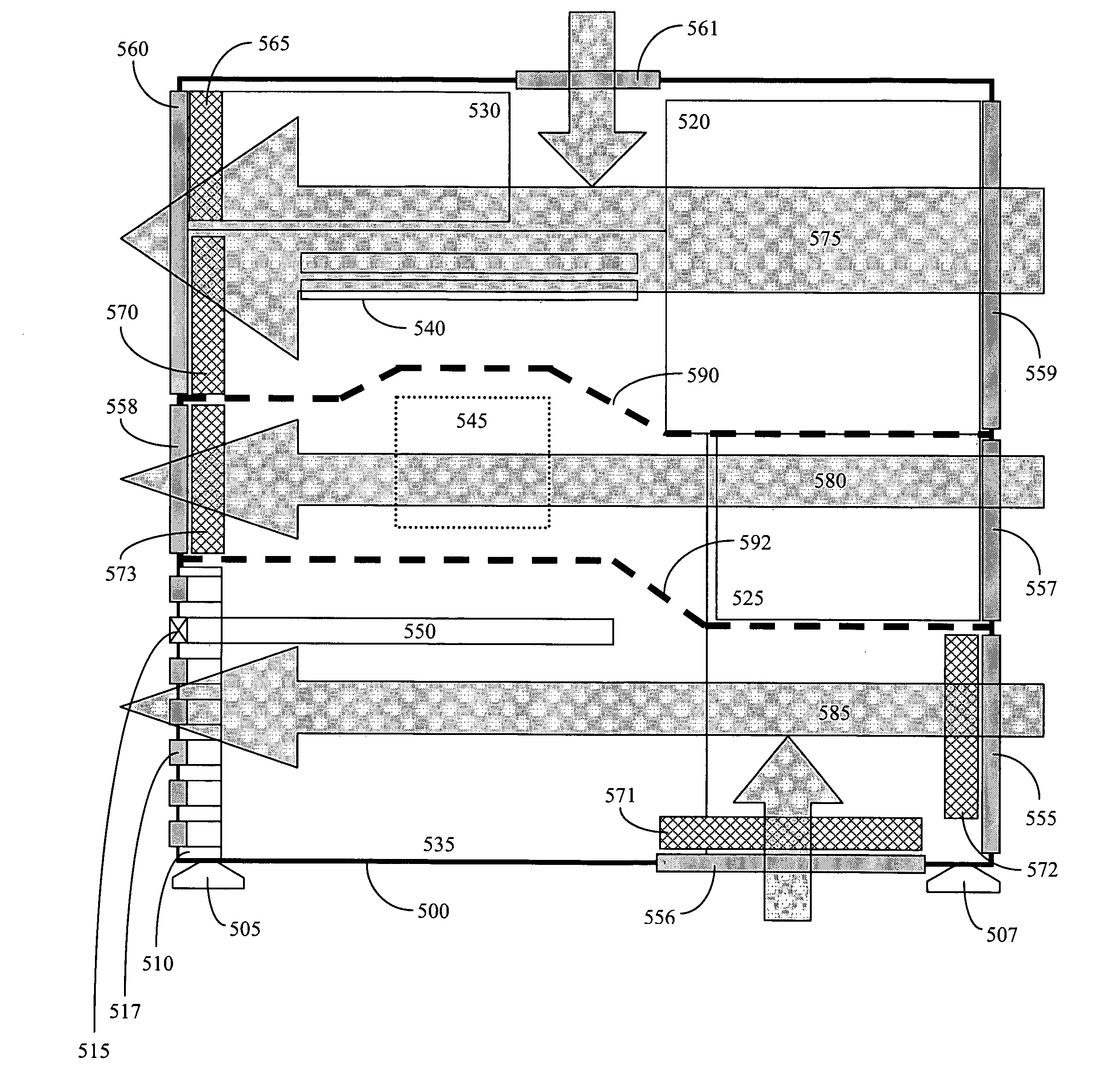
The present invention provides a computer chassis that improves airflow and reduces trapped air pockets, thereby increasing heat transfer from components of the computer system. The chassis has multiple chambers separated by partitions, and each chamber has at least one vent for introducing air and at least one vent for exhausting air. The chambers are coupled to air vents through which air enters and exits the chamber. The invention also includes a device for causing air to flow through the chambers. The computer chassis reduces the occurrence of trapped air pockets and increases heat transfer from components of the chassis, thereby improving the reliability and performance of each component within the computer system.

Problems solved by technology

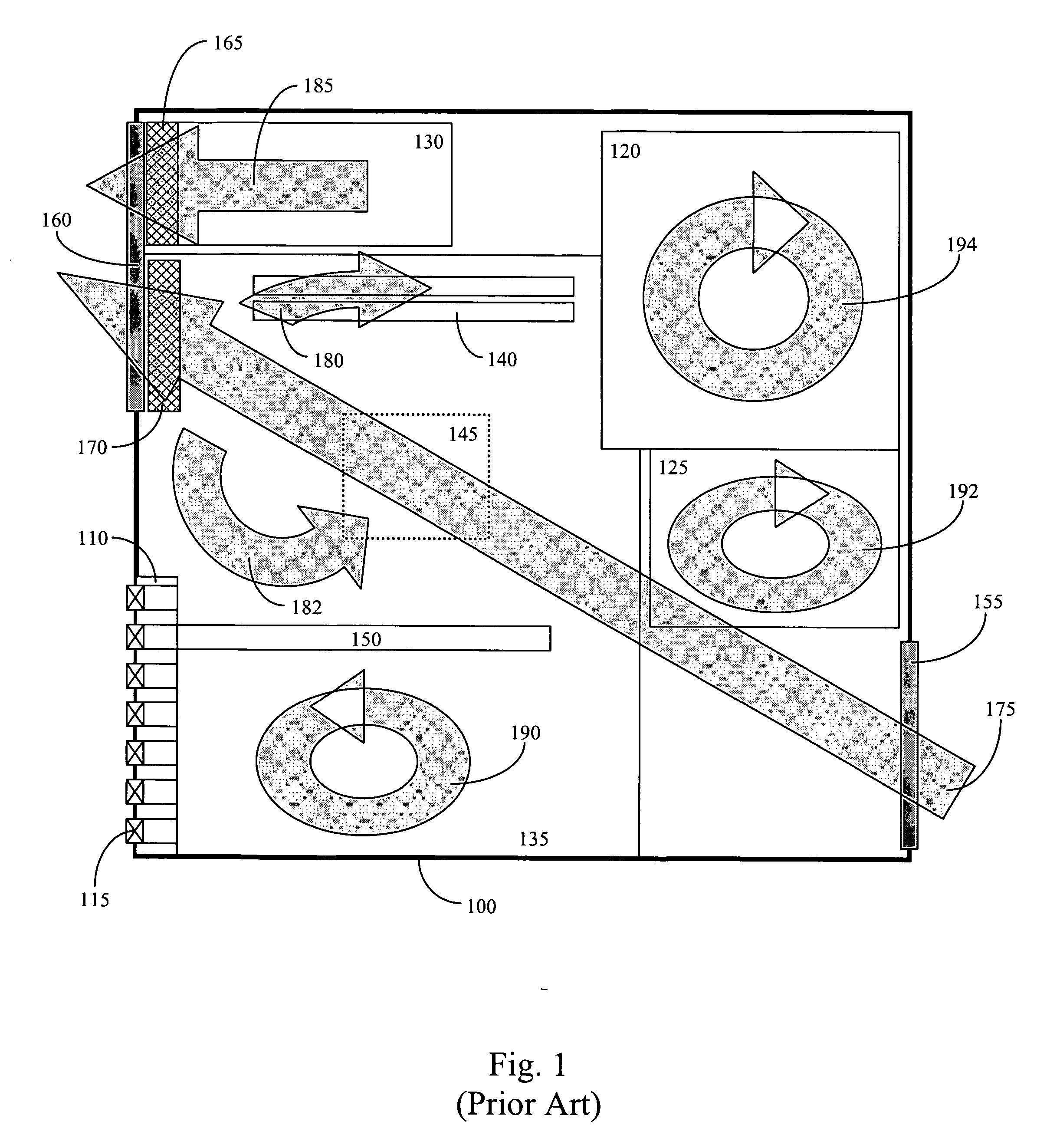
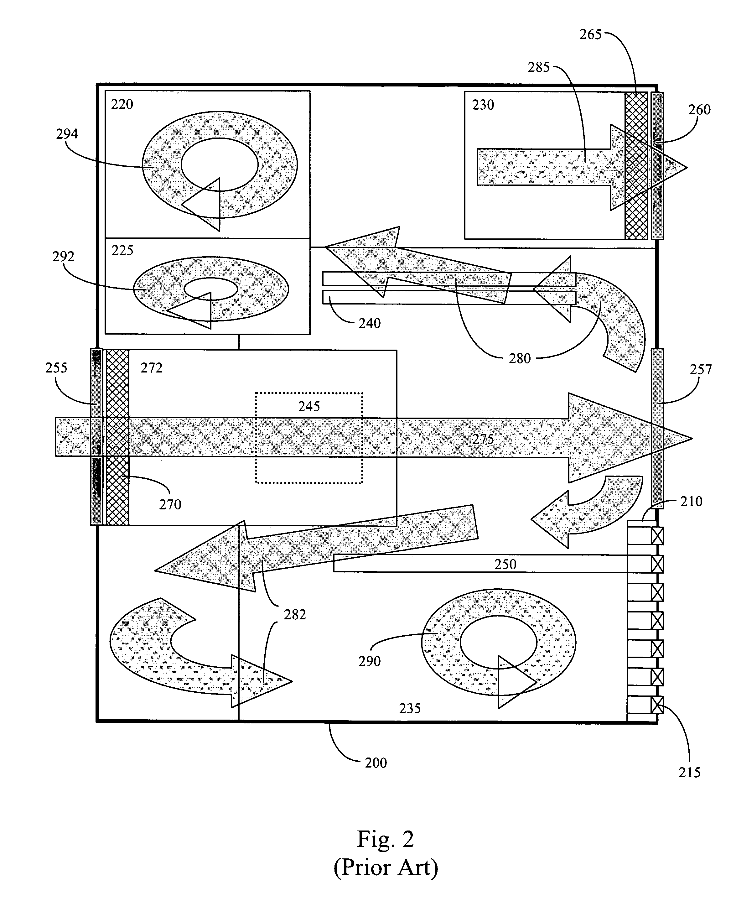
Not only does the recirculation of hot air within the chassis reduce the reliability and performance of most components, but it also significantly reduces the potential heat dissipation from each component by increasing the ambient air temperature within the chassis.
As such, a chassis in accordance with the ATX specification creates a significant reliability and performance bottleneck for system builders.

Method used


Image

  • Computer chassis for improved airflow and heat transfer from computer system components
  • Computer chassis for improved airflow and heat transfer from computer system components
  • Computer chassis for improved airflow and heat transfer from computer system components

Examples


Embodiment Construction

[0023] Reference will now be made in detail to the preferred embodiments of the present invention, examples of which are illustrated in the accompanying figures. While the invention will be described in conjunction with the preferred embodiments, it will be understood that they are not intended to limit the invention to these embodiments. On the contrary, the invention is intended to cover alternatives, modifications, and equivalents, which may be included within the spirit and scope of the invention as defined by the appended claims. Furthermore, in the following detailed description of embodiments of the present invention, numerous specific details are set forth in order to provide a thorough understanding of the present invention. However, it will be recognized by one of ordinary skill in the art that the present invention may be practiced without these specific details. In other instances, well-known methods, procedures, components, and circuits have not been described in detail...


PUM


Abstract

The present invention pertains to a computer chassis with improved airflow to reduce the occurrence of trapped air pockets and increase heat transfer from components within the chassis. The computer chassis includes a plurality of chambers, wherein each of the chambers is separated by a partition. The partitions are operable to reduce the occurrence of trapped air pockets and increase heat transfer from components of the chassis by causing air to flow through each of the chambers. The computer chassis further includes at least two air vents, wherein each of the chambers is coupled to at least one of the at least two air vents through which air enters the chamber, and wherein each of the chambers is coupled to at least one of the at least two air vents through which air exits the chamber.

Description

FIELD OF THE INVENTION [0001] The field of the present invention relates to chassis design for electronic devices, e.g., computer systems, and more particularly to systems for improved cooling of components housed in computer chassis. BACKGROUND OF THE INVENTION [0002] Over the past ten years, the amount of heat generated by individual components within computer systems has increased dramatically. For example, in 1995 when Intel Corporation introduced the ATX form factor specification, central processing units (CPUs) dissipated around 10 watts of heat. Some ten years later when Intel introduced the BTX form factor specification, CPUs dissipated nearly 150 watts of heat. Along the same lines, the average high-performance graphics card now dissipates around 80 watts of heat, whereas graphics cards from 1995 dissipated about one-tenth that amount. As such, it is becoming increasingly more important to adequately cool high-power components within the computer chassis to ensure reliabili...

Claims


Application Information

Patent Timeline
Patent Type & Authority Applications(United States)
IPC IPC(8): H05K7/20
CPCH05K7/20727
Inventor WAGNER, BARRY A.LE, DONTSU, WILLIAM P.
Owner NVIDIA CORP
Learn More