
Liquid cartridge

a liquid cartridge and liquid technology, applied in the field of liquid cartridges, can solve the problems of reducing the effective use of ink, and reducing the volumetric efficiency of ink, so as to prevent the viscosity of liquid from being raised, improving the volumetric efficiency of liquid, and maintaining a constant degree of degassing

Inactive Publication Date: 2007-06-14
SEIKO EPSON CORP
View PDF3 Cites 23 Cited by
  • Summary
  • Abstract
  • Description
  • Claims
  • Application Information

AI Technical Summary

Benefits of technology

[0012] An advantage of some aspects of the invention is to provide a liquid cartridge which can improve volumetric efficiency of a liquid while preventing viscosity of the liquid from being raised and keeping a degree of degassing constant.
[0015] With this configuration, since the air communicating path communicating the internal space within the cartridge case with atmosphere is formed to surround the internal space, water accommodated in the liquid accommodating part can be prevented from being evaporated, thereby allowing viscosity of the liquid to be effectively prevented from being raised, compared to a configuration where the air is directly introduced from the air introduction hole into the internal space. In addition, it can be effectively prevented that a degree of degassing is lowered due to bubbles produced in the ink pack. Accordingly, it is possible to form the liquid accommodating part (all or some) made of flexible material (for example, resin film or rubber) without using an aluminum laminate film to prevent viscosity of the liquid from being raised and keep a degree of degassing constant. Accordingly, it is possible to accommodate the liquid of the substantially same volume as the internal space in the liquid accommodating part, which results in improvement of an ink volumetric efficiency. That is, in this configuration, since the liquid accommodating part can be formed by deformable material (in other words, material apt to be pressed down by the introduced air), a negative pressure can be suppressed from being raised when the amount of liquid remaining in the liquid accommodating part is reduced, thereby allowing exhaustion of the liquid.
[0017] With this configuration, the air communicating path is formed by sealing an opening of a shallow groove formed on an edge of the opening of the case body with the lid member. That is, the air introduced from the air introduction hole is introduced into the internal space after going around the internal space via the air communicating path. Accordingly, viscosity of liquid in the liquid accommodating part can be prevented from being raised and a degree of degassing can remain constant.
[0019] With this configuration, the air communicating path is formed by sealing an opening of a groove defined by the external case and the internal case in a substantially annular shape at a periphery of the case body with the lid member. That is, the air introduced from the air introduction hole is introduced into the internal space after going around the internal space (the periphery of the case body) via the air communicating path. Accordingly, viscosity of liquid in the liquid accommodating part can be prevented from being raised and a degree of degassing can remain constant.
[0021] With this configuration, the air communicating path, i.e., the internal space, can be shielded from the outside in a preserved condition of the liquid cartridge (that is, before the liquid cartridge is mounted). Accordingly, even in the preserved condition of the liquid cartridge, viscosity of liquid can be prevented from being raised and a degree of degassing can remain constant.
[0025] With this configuration, since the liquid pack is made of a flexible resin film or rubber, a negative pressure can be suppressed from being raised when the amount of liquid remaining in the liquid pack is reduced.

Problems solved by technology

However, the structure disclosed in Patent Document 1 has a problem in that, since the foam is impregnated (absorbed and held) with ink, the quantity of ink which can be accommodated in the cartridge is reduced by the volume of the foam, thereby decreasing an ink volumetric efficiency, and an effective usage of ink is reduced since unused ink remains in the foam.
This may cause a problem of lowering of an ink volumetric efficiency due to an empty space occurring inside the ink cartridge receiving the ink bag.

Method used


Image

  • Liquid cartridge
  • Liquid cartridge
  • Liquid cartridge

Examples


first embodiment

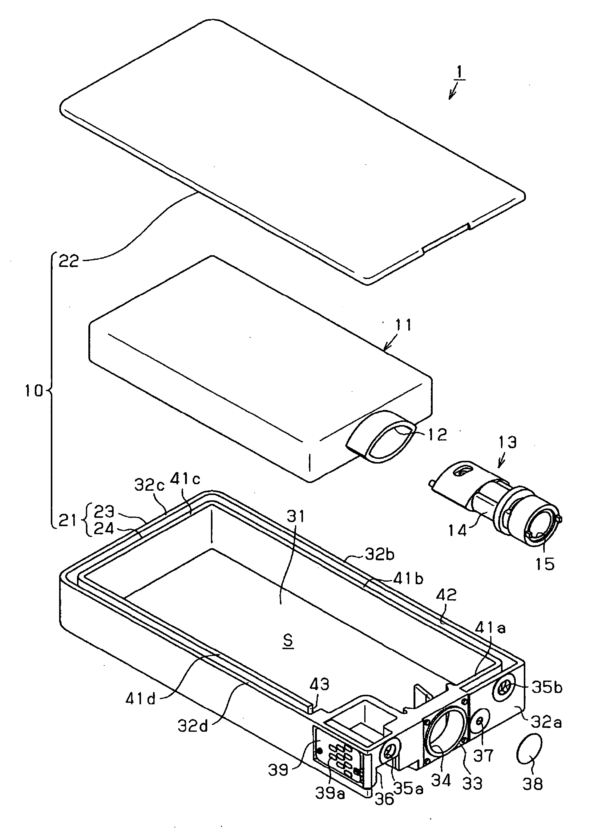
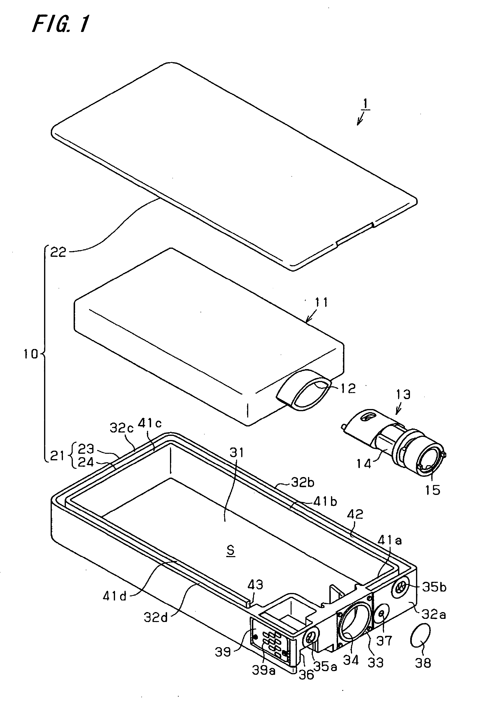
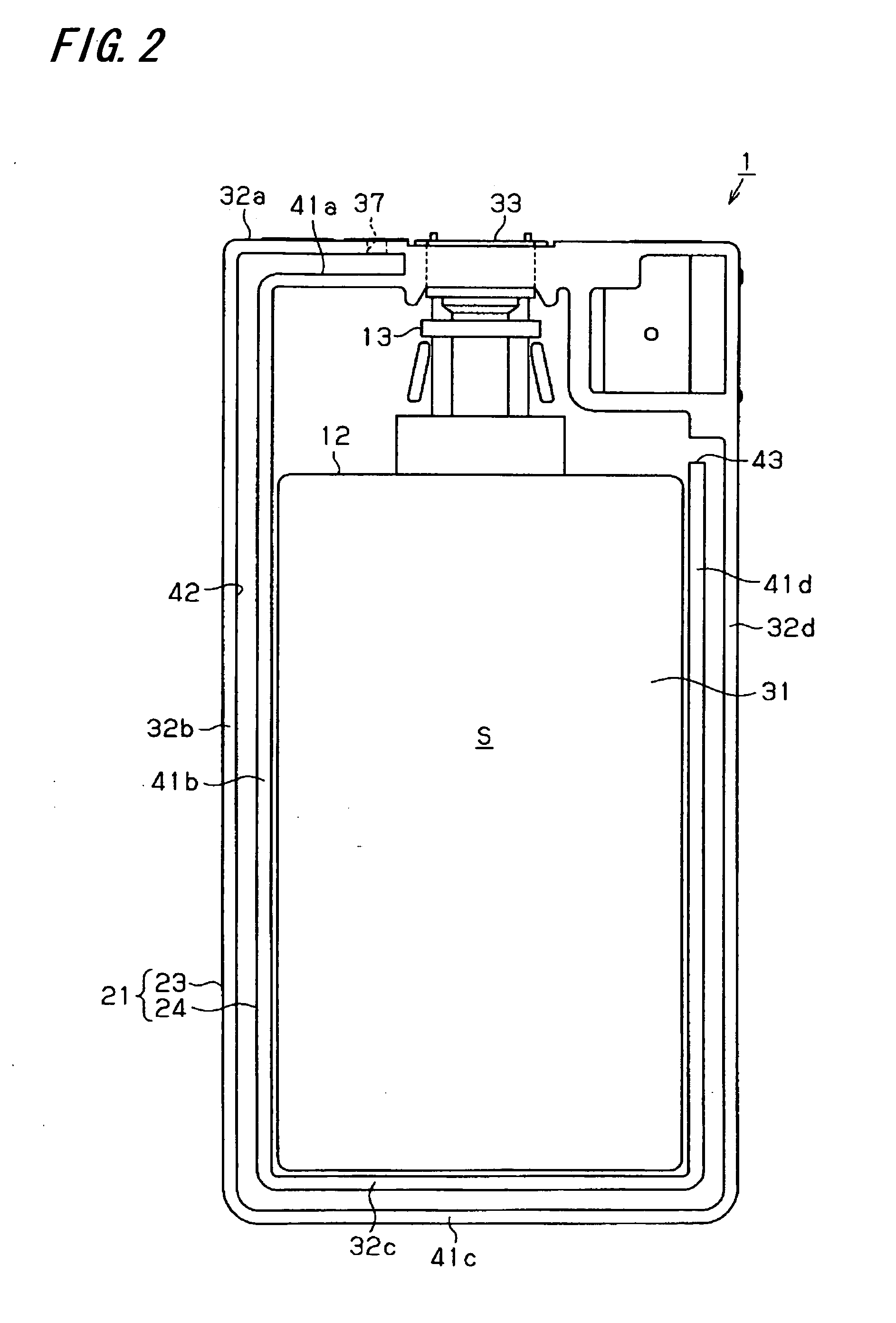
[0039] Hereinafter, an inkjet cartridge for supplying ink to a recording head of an inkjet type recording apparatus, for example, according to a first embodiment of the present invention will be described with reference to FIGS. 1 to 4. In this embodiment, the liquid cartridge will be illustrated with an ink cartridge, however, may be a liquid cartridge used for liquid ejecting apparatuses that eject liquid other than ink. For example, the liquid cartridge may be a liquid cartridge used for a liquid ejecting apparatus that ejects electrode material (conductive paste) or color material used to manufacture a liquid crystal display, an organic electro-luminescence (EL) display, a field emission display (FED) and soon, a liquid ejecting apparatus that ejects bio organic matter used to manufacture a biochip, or a precision pipette sample ejecting apparatus, and so on.

[0040]FIG. 1 is an exploded perspective view of an ink cartridge 1 of the first embodiment, FIG. 2 is a plan view showing...

second embodiment

[0069] Next, a second embodiment of the present invention will be described with reference to FIGS. 5 and 6, with focused on differences from the first embodiment. The second embodiment has the same configuration as the first embodiment except a configuration of the liquid accommodating part of the ink cartridge. Therefore, the same elements as in the first embodiment are denoted by the same reference numerals and detailed description thereof will be omitted.

[0070]FIG. 5 is an exploded perspective view of the ink cartridge 51 according to the second embodiment and FIG. 6 is a plan view showing the interior of the ink cartridge 51.

[0071] As shown in FIG. 5, the ink cartridge 51 has a box-shaped cartridge case 60. Similarly to the first embodiment, the cartridge case 60 comprises a box-shaped case body 71 with its top side opened and a rectangular lid member 22 covering the opening of the case body 71, both of which are made of synthetic resin (for example, polypropylene). With the ...


PUM


Abstract

A liquid cartridge includes: a cartridge case including a case body having an opening at its one side and a lid member covering the opening of the case body; and a liquid accommodating part that is provided in an internal space defined within the cartridge case, at least a part of the liquid accommodating part being made of flexible material, wherein an air communicating path having one end communicating with an air introduction hole through which air is introduced and the other end communicating with the internal space is formed to surround the internal space in the cartridge case.

Description

BACKGROUND [0001] 1. Technical Field [0002] The present invention relates to a liquid cartridge, and more specifically, to a liquid cartridge which is adapted to supply liquid to a liquid ejecting apparatus. [0003] 2. Related Art [0004] In the related art, an inkjet type recording apparatus (hereinafter simply referred to as a recording apparatus) has been widely used as one kind of liquid ejecting apparatus having a liquid ejecting head from which liquid is ejected to a target. This recording apparatus, including a carriage and a recording head as the liquid ejecting head mounted on the carriage, performs a recording operation for a recording medium as a target by discharging ink as the liquid from a nozzle formed in the recording head while moving the carriage with respect to the recording medium. [0005] In this recording apparatus, typically, ink to be discharged from the recording head is accommodated in an ink cartridge as a liquid cartridge. When the ink cartridge is mounted o...

Claims


Application Information

Patent Timeline
IPC IPC(8): B41J2/175
CPCB41J2/17513
Inventor SATO, SEIYA
Owner SEIKO EPSON CORP
Learn More