
System for reducing second order intermodulation products from differential circuits

a differential circuit and product technology, applied in the field of communication, can solve the problems of prohibitive cost of manufacturing these rf devices, relatively new, complex, and difficult to achieve, and achieve the effect of reducing intermodulation products

Active Publication Date: 2007-06-14
ICERA CANADA ULC
View PDF13 Cites 46 Cited by
  • Summary
  • Abstract
  • Description
  • Claims
  • Application Information

AI Technical Summary

Benefits of technology

[0024] It is an object of the present invention to obviate or mitigate at least one disadvantage of previous differential CMOS passive mixer circuits. In particular, it is an object of the present invention to balance the differential signal paths of a CMOS passive mixer circuit to reduce intermodulation products.

Problems solved by technology

The RF signal is mixed with a local oscillator at the carrier frequency, therefore there is no image frequency, and no image components to corrupt the signal, which prove problematic for the other architectures.
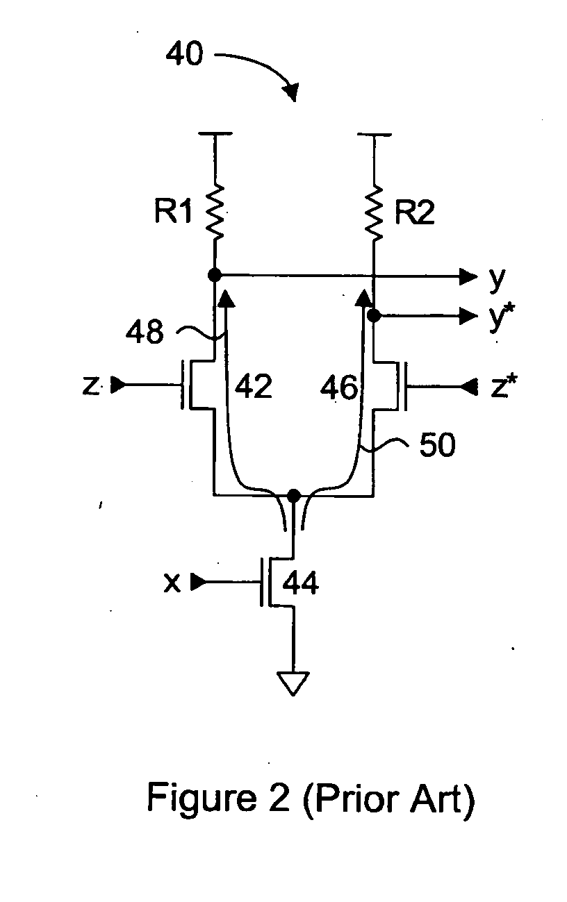
A problem with this circuit lies in the non-linear nature of input transistor 44, which will generate an output y / y* having undesired intermodulation products.
This mis-match can cause the second order intermodulation products to appear.
These technologies provide certain advantages for RF circuits, but are relatively new, very complex, and hence expensive.
Consequently, the costs for manufacturing these RF devices can be prohibitive.
Unfortunately, direct replacement of the bipolar transistors with CMOS transistors in the mixer circuits of FIG. 4 will add significant noise, which is undesirable.
This DC current will add significant amounts of noise, which will degrade the SNR of the receiver.
Even if the level of noise could be reduced to tolerable levels, the circuit path mismatch issues would still apply and may result in the generation of the second order intermodulation products.
However, potential CMOS transistor mismatch can contribute to circuit path mismatch even in a symmetrical circuit layout.
Tight transistor threshold voltage control is more easily obtained with larger sized transistors, however, larger sized transistors impose bandwidth limitations in addition to increased power consumption.

Method used


Image

  • System for reducing second order intermodulation products from differential circuits
  • System for reducing second order intermodulation products from differential circuits
  • System for reducing second order intermodulation products from differential circuits

Examples


Embodiment Construction

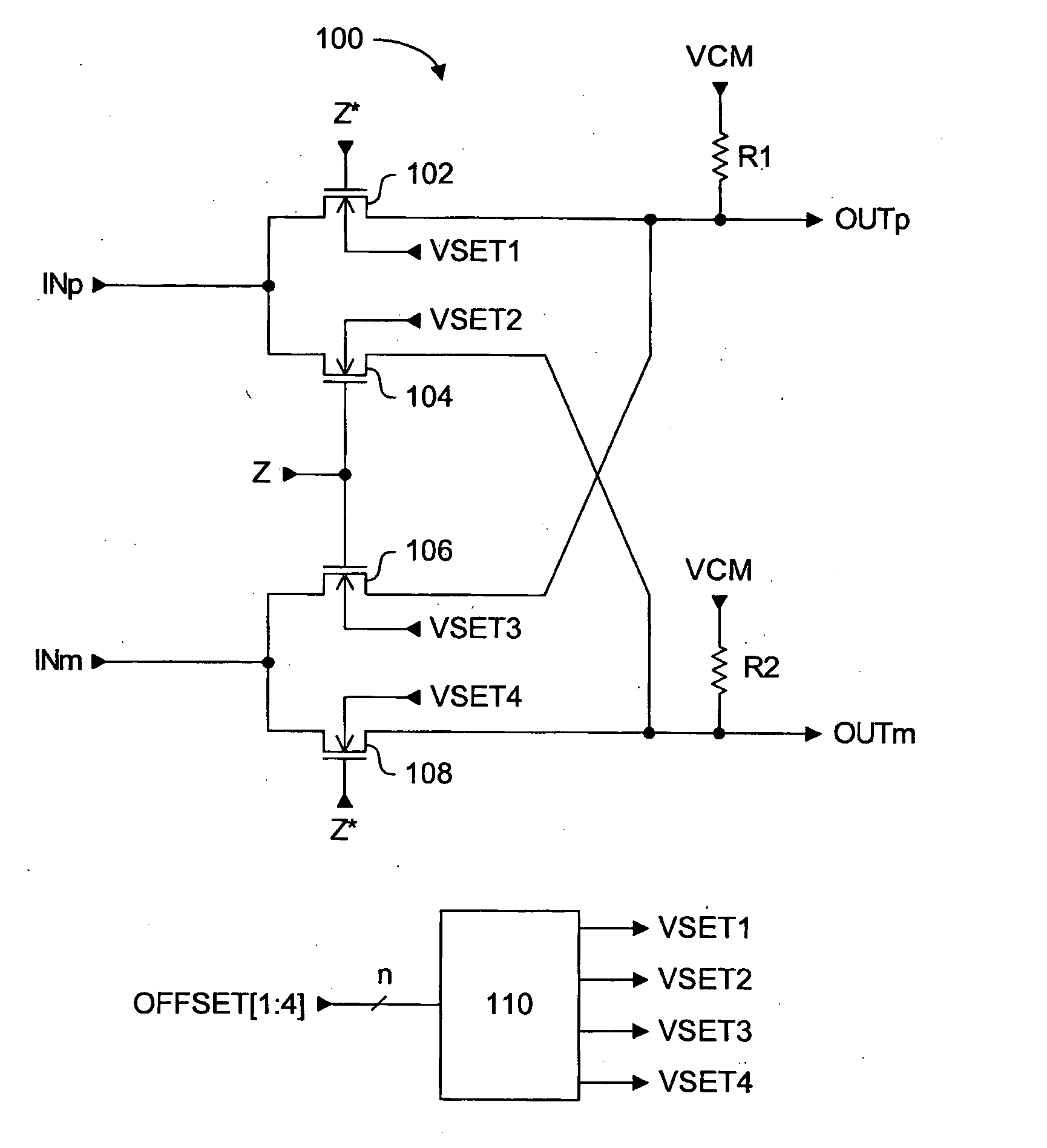
[0043] Generally, the present invention provides a passive CMOS differential mixer circuit with a mismatch correction circuit for balancing the electrical characteristics of the two output paths. Once the output paths of the differential circuit are balanced, or matched as closely as possible, second order intermodulation product generation can be inhibited or at least reduced to acceptable levels. The mismatch correction circuit receives at least one n-bit digital offset signal, to generate one or more corresponding voltages. The generated voltages are applied to the differential mixer circuit to balance its electrical characteristics.

[0044] According to embodiments of the present invention, the voltage signals can be applied to the back gate bias voltages of selected transistors of the circuit to adjust their threshold voltages such that they all match. Alternately, the voltage signals can adjust common mode voltages applied directly to a selected signal path to ensure that their...


PUM


Abstract

A passive CMOS differential mixer circuit with a mismatch correction circuit for balancing the electrical characteristics of the two output paths. Once the output paths of the differential circuit are balanced, or matched as closely as possible, second order intermodulation product generation can be inhibited or at least reduced to acceptable levels. The mismatch correction circuit receives a digital offset signal, and generates one or more voltage signals to be selectively applied to the signal paths of the passive differential mixer circuit. The voltage signals can be adjusted back gate bias voltages applied to the bulk terminals of selected transistors to adjust their threshold voltages, or the voltage signals can be adjusted common mode voltages applied directly to a selected signal path. Since the differential mixer circuit is passive, no DC current contribution to noise is generated. The switching transistors of the mixer circuit can be maintained at minimal dimensions to reduce switching signal drive loading, resulting in lower power consumption and higher operating frequencies than if larger switching transistors were used.

Description

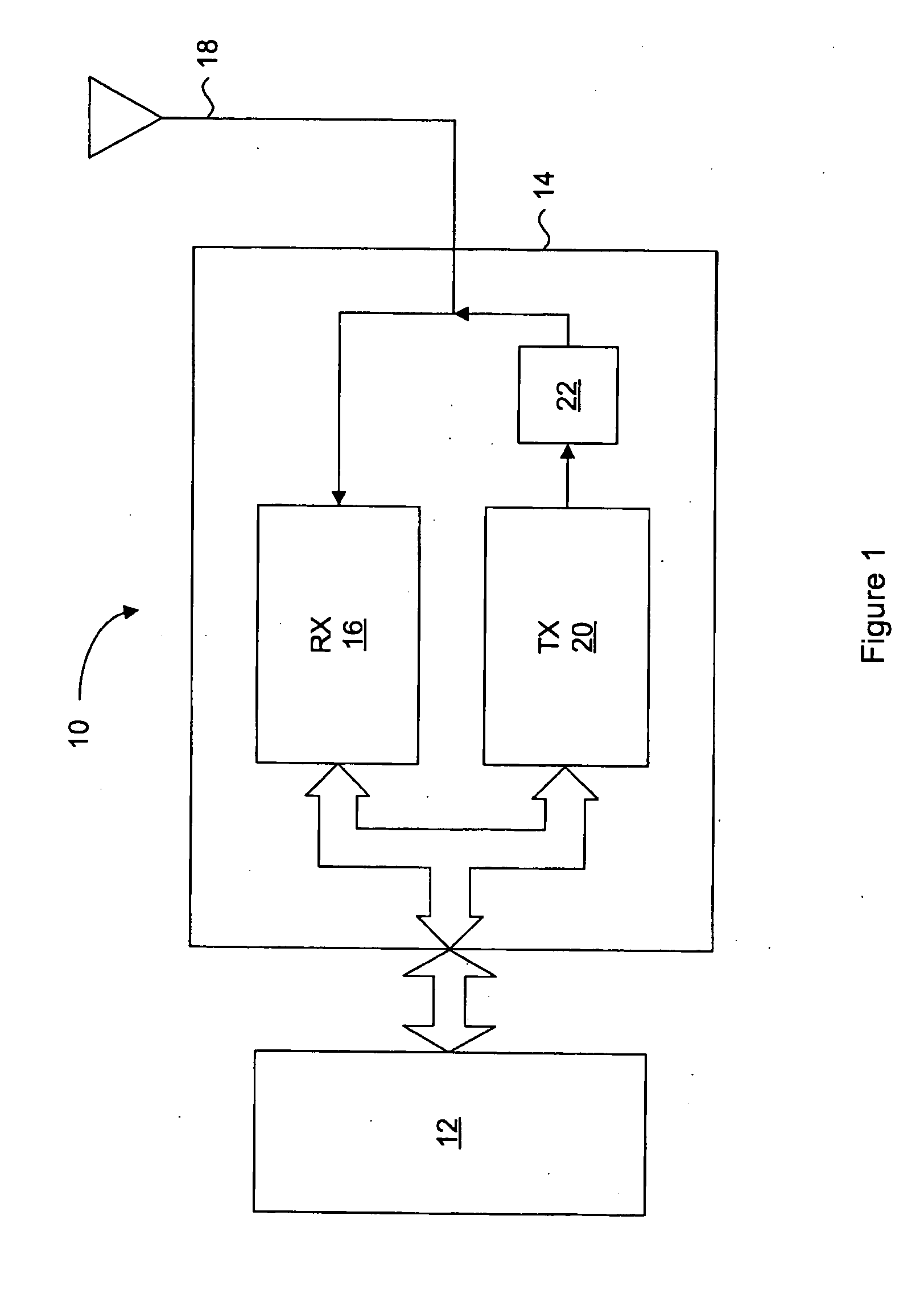
FIELD OF THE INVENTION [0001] The present invention relates generally to communications, and to down-conversion of an RF signal to a lower frequency in a radio. More specifically, the present invention relates to passive mixers of direct-conversion receivers. BACKGROUND OF THE INVENTION [0002] Wireless devices have been in use for many years for enabling mobile communication of voice and data. Such devices can include mobile phones and wireless enabled personal digital assistants (PDA's) for example. FIG. 1 is a generic block diagram of the core components of such wireless devices. The wireless core 10 includes a base band processor 12 for controlling application specific functions of the wireless device and for providing and receiving voice or data signals to a radio frequency (RF) transceiver chip 14. The RF transceiver chip 14 is responsible for frequency up-conversion of transmission signals, and frequency down-conversion of received signals. RF transceiver chip 14 includes a re...

Claims


Application Information

Patent Timeline
Patent Type & Authority Applications(United States)
IPC IPC(8): G06F7/44
CPCH03D7/1441H03D7/1433H03D7/1458H03D7/1466H03D2200/0047H03D2200/0088
Inventor EMBABI, SHERIF H.K.HOLDEN, ALAN R.JAEHNIG, JASON P.BELLAOUAR, ABDELLATIF
Owner ICERA CANADA ULC
Learn More