
Tubular plasma display

a tubular plasma and display panel technology, applied in the direction of gas discharge electrodes, gas discharge vessels/containers, gas-filled discharge tubes, etc., can solve the problems of large reduction in manufacturing costs, no advancement in the performance of initial fiber-based work, complex and costly manufacturing, etc., to achieve tight dimensionality, increase the brightness of room contrast, and large tubular plasma displays

Inactive Publication Date: 2007-06-14
MOORE CHAD B
View PDF55 Cites 21 Cited by
  • Summary
  • Abstract
  • Description
  • Claims
  • Application Information

AI Technical Summary

Benefits of technology

[0023] The present invention includes a new tubular plasma display that can be very economically manufactured in very large sizes, that is very light weight, incorporates a color filter to solve the bright room contrast issue and can be rolled or bent.
[0025] Each tube in the plasma tube array preferably contains at least one wire electrode, a hard emissive coating (containing carbon nanotubes in one embodiment), and a color phosphor and is individually sealed containing a plasma gas. Polymer-based color filter coatings may also be applied to the surface of the plasma tubes after they are gas processed and sealed to drastically increase the bright room contrast, brightness, and color purity of the display. The plasma tubes are preferably created using hot glass extrusion followed by a tube draw, therefore tight dimensional control is obtained and the intra pixel shape may be tailored to provide for the most efficient plasma kinetics.

Problems solved by technology

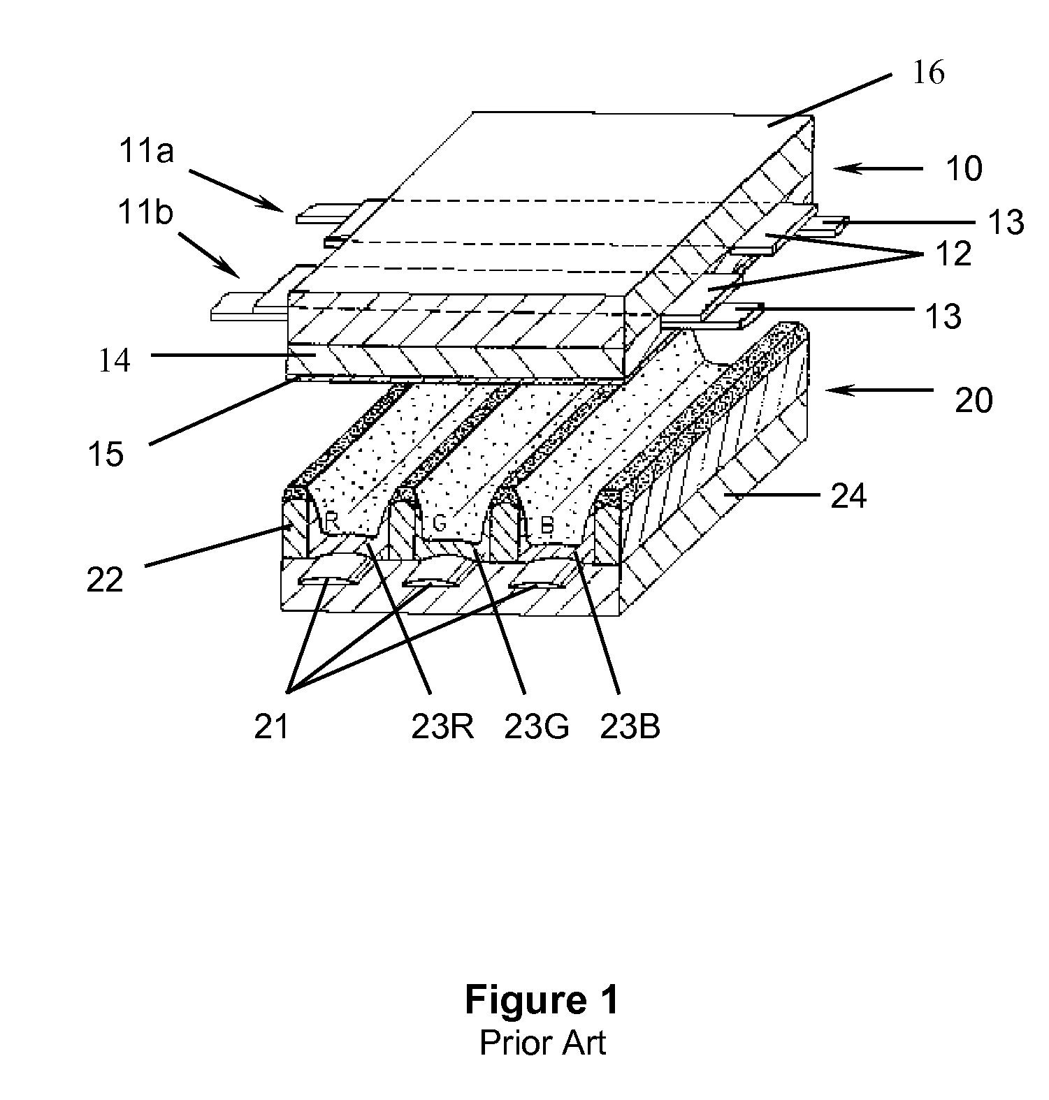
The three electrode surface discharge structure, shown in FIG. 1, advances many technical attributes of the display, but its complex manufacturing process and detailed structure makes manufacturing complicated and costly.
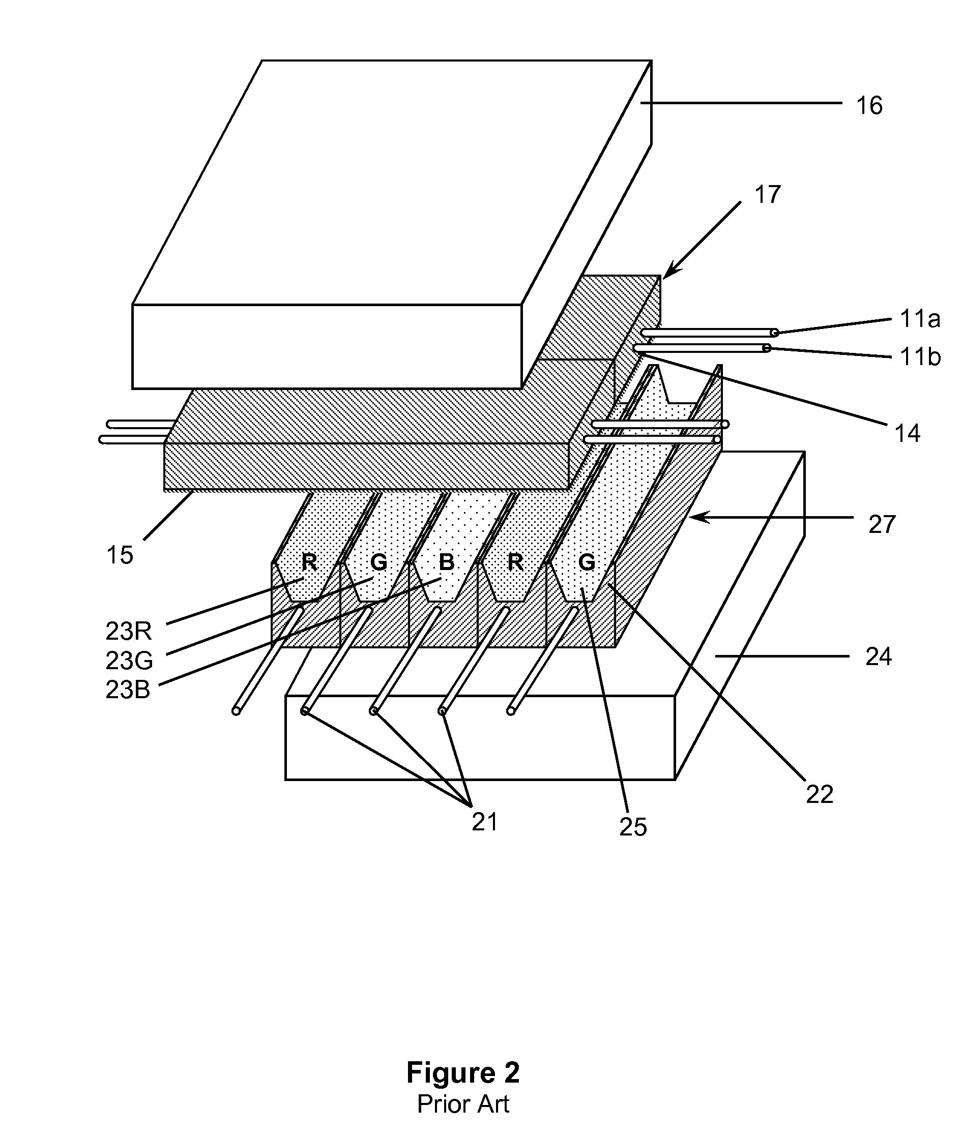
Although using fibers to create the structure in a display has drastically simplified the manufacturing of the panel leading to a large reduction in manufacturing cost, the initial fiber-based work had no advancements to the performance of the display.

Method used


Image

  • Tubular plasma display
  • Tubular plasma display
  • Tubular plasma display

Examples


Embodiment Construction

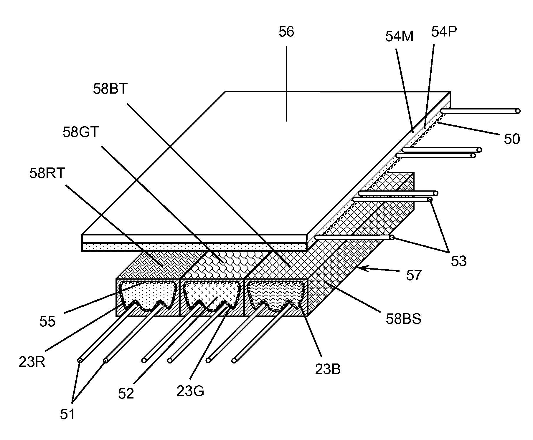
[0095] In one embodiment of the present invention, a tubular plasma display (TPD) includes an electroded sheet (eSheet) attached to an array of plasma tubes, as shown in FIG. 7. The electroded sheet 56 is a polymer substrate 54 containing wire electrodes 53. The plasma tubes 57 contain wire electrodes 51, a hard emissive coating 55, a phosphorescent material 23 and a plasma gas capable of generating ultraviolet light. Color filter coatings 58RT, 58GT, 58BT are added to the top of the plasma tube 57 and a black matrix 58BS is added to the sides of the plasma tubes 57. The electroded sheet 56 is directly bonded to the array of plasma tubes 57, where the wire sustain electrodes 53 in the electroded sheet 56 are nominally orthogonal to the wire address electrodes 51 in the plasma tubes 57. Using wire electrodes in both the electroded sheet 56 and the tubes 57 allows for low cost manufacturing and high quality operation of very large plasma displays. The wire electrodes are preferably co...


PUM


Abstract

A tubular plasma display (TPD) is composed of an electroded sheet (electroded sheet) attached to an array of plasma tubes. Both the electrode sheet and the plasma tube array contain wire electrodes, which create very electrically conductive lines and the ability to address very large displays. The electroded sheet is composed of a thin flexible polymer substrate with embedded wire sustain electrodes. Each plasma tube is individually sealed and contains a wire address electrode, a hard emissive coating, a color phosphor and a Xenon based plasma gas. Polymer-based color filter coatings may also be applied to the surface of the plasma tubes after they are gas processed and sealed to drastically increase the bright room contrast, brightness, and color purity of the display.

Description

REFERENCE TO RELATED APPLICATIONS [0001] This application claims an invention that was disclosed in one or more of the following provisional applications: [0002] 1) Provisional Application Number Provisional Application No. 60 / 749,446, filed Dec. 12, 2005, entitled “ELECTRODE ADDRESSING PLANE IN AN ELECTRONIC DISPLAY”; [0003] 2) Provisional Application No. 60 / 759,704, filed Jan. 18, 2006, entitled “ELECTRODE ADDRESSING PLANE IN AN ELECTRONIC DISPLAY AND PROCESS”; [0004] 3) Provisional Application No. 60 / 827,146, filed Sep. 27, 2006, entitled “TUBULAR PLASMA DISPLAY”; [0005] 4) Provisional Application No. 60 / 827,152, filed Sep. 27, 2006, entitled “ELECTRODED SHEET”; and [0006] 5) Provisional Application No. 60 / 827,170, filed Sep. 27, 2006, entitled “WIRE-BASED FLAT PANEL DISPLAYS”. [0007] The benefit under 35 USC §119(e) of the United States provisional applications is hereby claimed, and the aforementioned applications are hereby incorporated herein by reference.BACKGROUND OF THE IN...

Claims


Application Information

Patent Timeline
IPC IPC(8): H01J17/49H01J11/00
CPCH01J11/00H01J11/12H01J11/22H01J11/36H01J11/38H01J2211/444
Inventor MOORE, CHAD B.
Owner MOORE CHAD B
Learn More