
Wireless sensor antenna configuration

a technology of wireless sensor and antenna, applied in the direction of generator/motor, simultaneous indication of multiple variables, instruments, etc., can solve the problems of poor pressure sensor, inability to maintain constant and ideal temperature, and inability to resist changes, so as to prevent noise, reduce the large effect of inductive coupling

Inactive Publication Date: 2007-06-14
HONEYWELL INT INC
View PDF11 Cites 8 Cited by
  • Summary
  • Abstract
  • Description
  • Claims
  • Application Information

AI Technical Summary

Benefits of technology

[0020] It is an aspect of certain embodiments to use a shielding technique wherein a guard ring can be placed around either the acoustic wave device or the spiral inductor. A guard ring is a conductive trace surrounding, or nearly surrounding, a circuit element. The guard ring is usually connected to circuit ground and thereby helps prevent noise from reaching the enclosed circuit element or from escaping from the enclosed circuit element. Guard rings are most effective in protecting coplanar elements, meaning they geometrically lie substantially on the same plane, from one another. In many cases, circuit elements are exposed to noise sources that are not coplanar, in which case a shield of conductive material is used. The shield substantially encloses the circuit elements. A guard ring can be thought of as a two dimensional shield that works in special circumstances.
[0021] It is an aspect of some embodiments to use geometric shielding. Historically, the simplest type of shielding, called “one over r squared shielding” is to place a sensitive component far from noise sources. Distance, however, is rarely available in a compact system and rarely appropriate for real world situations. A small amount of distance can have a large effect in some circumstances. As dictated by the laws of physics, the fundamental frequency, discussed above, is inversely related to a fundamental wavelength. Separating the acoustic wave device and the spiral inductor by a few fundamental wavelengths can have a large effect on inductive coupling.
[0022] Inductive coupling occurs most efficiently when the electromagnetic fields of two or more inductive circuit elements line up. Misaligning the fields can significantly reduce inductive coupling. Rotation and lateral shifts can cause significant misalignment and thereby reduce the inductive coupling.

Problems solved by technology

Pressure can cause it to flex.
Temperature can also cause resistance changes.
As such, the pressure sensor gives poor results is the temperature isn't constant and ideal.
Many sensors can not be advantageously employed unless an interrogation circuit is also employed.
Devices designed for coupling efficiency can lack sensitivity.
Sensitive devices can couple poorly.
The problem, however, is that the acoustic wave device and the driver can both inductively couple with the interrogation circuit.
This can lead to a noisy sensor reading.
Another concern is that the driver and the acoustic wave device can inductively couple with one another, creating another source of noise in the sensor readings.

Method used


Image

  • Wireless sensor antenna configuration
  • Wireless sensor antenna configuration
  • Wireless sensor antenna configuration

Examples


Embodiment Construction

[0031] The particular values and configurations discussed in these non-limiting examples can be varied and are cited merely to illustrate at least one embodiment and are not intended to limit the scope thereof. In general, the figures are not to scale.

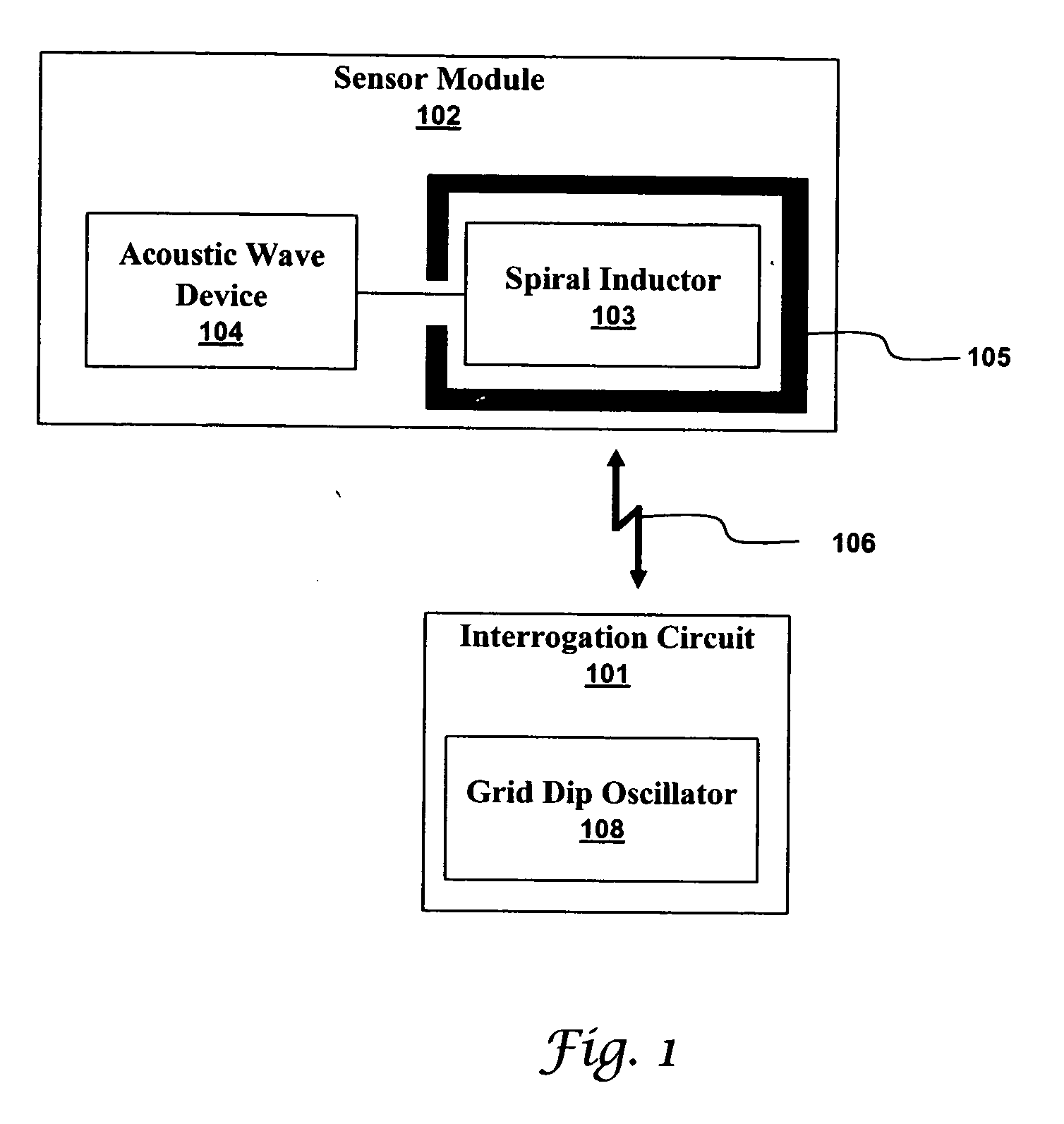
[0032]FIG. 1 illustrates a sensor module 102 inductively coupled to an interrogation circuit 101 in accordance with an embodiment. As discussed above, the interrogation circuit 101 can contain a grid dip oscillator (GDO) 108. The interrogation circuit 101 is inductively coupled to a spiral inductor 103 with the inductive coupling indicated by a two headed arrow 106. The spiral inductor 103 is surrounded by a guard ring 105 to minimize the coupling between the spiral inductor 103 and an acoustic wave device 105 to which it is electrically connected. In the system of FIG. 1, the acoustic wave device is open to noise sources other than the spiral inductor 103. Furthermore, the interrogation circuit 101 must be physically arranged to defe...


PUM


Abstract

Many sensors could be used in a passive wireless mode. These include RLC, acoustic wave and magneto-elastic sensors. These types of sensors are designed to exhibit a change in fundamental frequency when exposed to environmental factors such as temperature, pressure, or chemicals. An interrogation circuit can inductively couple to the sensor and measure the change in fundamental frequency. The change can be used to measure the environmental factor. Sensor sensitivity and inductive coupling efficiency can be competing design constraints. A driver, electrically connected to the sensor and inductively coupled to the interrogation circuit, can relax the constraints. The driver, however, can introduce noise into the sensor. The sensor can be shielded using physical and geometric techniques to reduce the noise.

Description

TECHNICAL FIELD [0001] Embodiments relate to sensors, sensor systems, and wireless interrogation. Embodiments also relate to passive wireless sensors and acoustic wave sensors. BACKGROUND OF THE INVENTION [0002] A variety of sensors are utilized to detect conditions, such as pressure and temperature. The ability to detect pressure and / or temperature is an advantage to any device exposed to variable pressure conditions, which can be severely affected by these conditions. An example of such a device is a catheter, which of course, can experience variations in both temperature and pressure. Many different techniques have been proposed for sensing the pressure and / or temperature passively and wirelessly. These technologies include LC tank, RC or RLC oscillator type, acoustic wave sensor, and magneto-elastic sensor. [0003] Acoustic wave devices often have one or two transducers arranged on a piezoelectric substrate. A transducer can convert an electrical input signal into an acoustic sig...

Claims


Application Information

Patent Timeline
IPC IPC(8): G01N29/36G01N27/02G01D5/12G08C19/06
CPCG01N27/025G01N27/725G01N29/022G01N29/2412G01N29/2462G01N29/34G01N29/36G01N2291/0255G01N2291/0256G01N2291/02863G01N2291/0423
Inventor LIU, JAMES ZT
Owner HONEYWELL INT INC
Learn More