
Vacuum cell thermal isolation for a phase change memory device

a phase change memory and vacuum cell technology, applied in the field of memory devices, can solve the problems of overly complex structure, low thermal isolation efficiency, and low thermal isolation efficiency of conventional designs, and achieve the effect of improving thermal isolation

Active Publication Date: 2007-06-07
MACRONIX INT CO LTD
View PDF98 Cites 220 Cited by
  • Summary
  • Abstract
  • Description
  • Claims
  • Application Information

AI Technical Summary

Benefits of technology

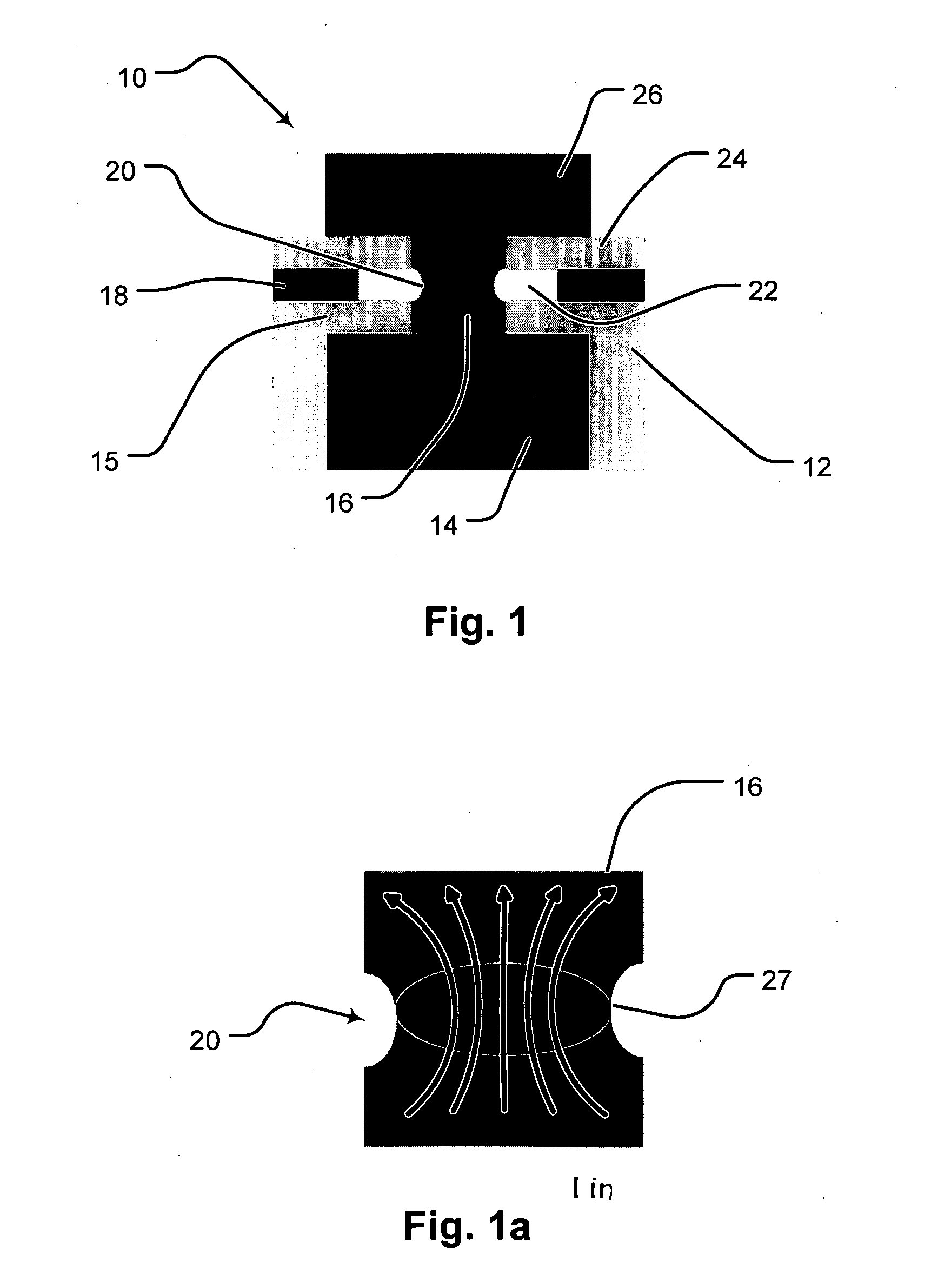
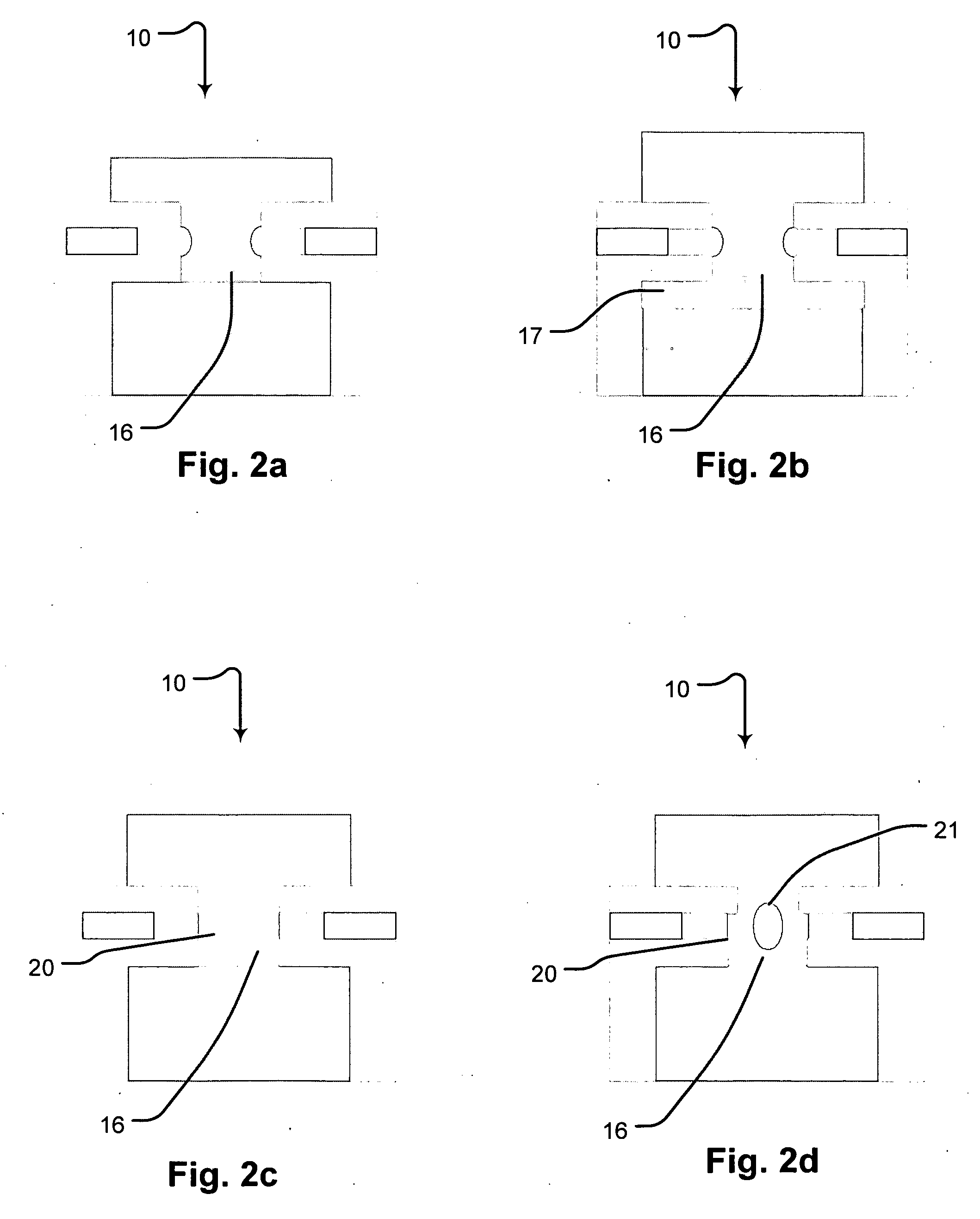
[0013] An important aspect of the claimed invention is a memory device with improved thermal isolation. The memory cell includes a first electrode element, having an upper surface; an insulator stack formed on the first electrode element, including first, second and third insulating members, all generally planar in form and having a central cavity formed therein and extending therethrough, wherein the second insulator member is recessed from the cavity; a phase change element, generally T-shaped in form, having a base portion extending into the cavity to make contact with the first electrode element and making contact with the first and third insulating members, and a crossbar portion extending over and in contact with the third insulating member, wherein the base portion of the phase change element, the recessed portions of the second insulating member and the surfaces of the first and third insulating members define a thermal isolation void; and a second electrode formed in contact with the phase change member.

Problems solved by technology

A specific issue arising from conventional the phase change memory and structures is the heat sink effect of conventional designs.
That structure, and the attendant fabrication process, is overly complex, yet it does not promote minimal current flow in the memory device.

Method used


Image

  • Vacuum cell thermal isolation for a phase change memory device
  • Vacuum cell thermal isolation for a phase change memory device
  • Vacuum cell thermal isolation for a phase change memory device

Examples


Embodiment Construction

[0018] The following discussion describes embodiments of the invention with particular reference to FIGS. 1-3. It will be understood that the examples and features shown are exemplary and illustrative in nature and not intended to limit the scope of the invention. That scope is defined solely by the claims appended hereto.

[0019] The present invention concerns memory elements and memory cells. As used herein, and as is well known in the art, a memory cell is a circuit device designed to hold a charge or state to indicate the logic level of a single data bit. Memory cells are arrayed to provide, for example, the random access memory for a computer. Within certain memory cells, a memory element performs the function of actually holding the charge or state. In a conventional dynamic random access memory cell, for example, a capacitor indicates the logic level of the cell, with a fully charged state indicating a logic 1, or high, state, and fully discharged indicating a logic 0, or low,...


PUM


Abstract

A memory device with improved thermal isolation. The memory cell includes a first electrode element, having an upper surface; an insulator stack formed on the first electrode element, including first, second and third insulating members, all generally planar in form and having a central cavity formed therein and extending therethrough, wherein the second insulator member is recessed from the cavity; a phase change element, generally T-shaped in form, having a base portion extending into the cavity to make contact with the first electrode element and making contact with the first and third insulating members, and a crossbar portion extending over and in contact with the third insulating member, wherein the base portion of the phase change element, the recessed portions of the second insulating member and the surfaces of the first and third insulating members define a thermal isolation void; and a second electrode formed in contact with the phase change member.

Description

REFERENCE TO RELATED APPLICATION [0001] This application claims the benefit of U.S. Provisional Patent Application No. 60 / 739,079 entitled “Improved Thermal Isolation for an Active-Sidewall Phase Change Memory Cell” filed on Nov. 21, 2005. That application is incorporated by reference for all purposes.PARTIES TO A JOINT RESEARCH AGREEMENT [0002] International Business Machines Corporation, a New York corporation; Macronix International Corporation, Ltd., a Taiwan corporation, and Infineon Technologies A.G., a German corporation, are parties to a Joint Research Agreement. BACKGROUND OF THE INVENTION [0003] 1. Field of the Invention [0004] The present invention relates generally to memory devices and more specifically to memory devices employing phase change element to store information. [0005] 2. Description of Related Art [0006] Phase change based memory materials are widely used in read-write optical disks, and such materials are seeing increasing use in computer memory devices. Th...

Claims


Application Information

Patent Timeline
IPC IPC(8): H01L29/94H01L29/76H01L31/00
CPCH01L45/06H01L45/1233H01L45/1246H01L45/1293H01L45/144H01L45/1625H01L45/1666H10N70/828H10N70/8616H10N70/231H10N70/026H10N70/061H10N70/8828H10N70/826
Inventor LUNG, HSIANG-LAN
Owner MACRONIX INT CO LTD
Learn More