
Remote test unit

a remote test and unit technology, applied in the field of communication network testing, can solve the problems of no convenient way to facilitate upper layer testing, and it is extremely difficult to determine if there is a defect in the cpe or the dslam

Inactive Publication Date: 2007-05-31
VEEX
View PDF9 Cites 37 Cited by
  • Summary
  • Abstract
  • Description
  • Claims
  • Application Information

AI Technical Summary

Benefits of technology

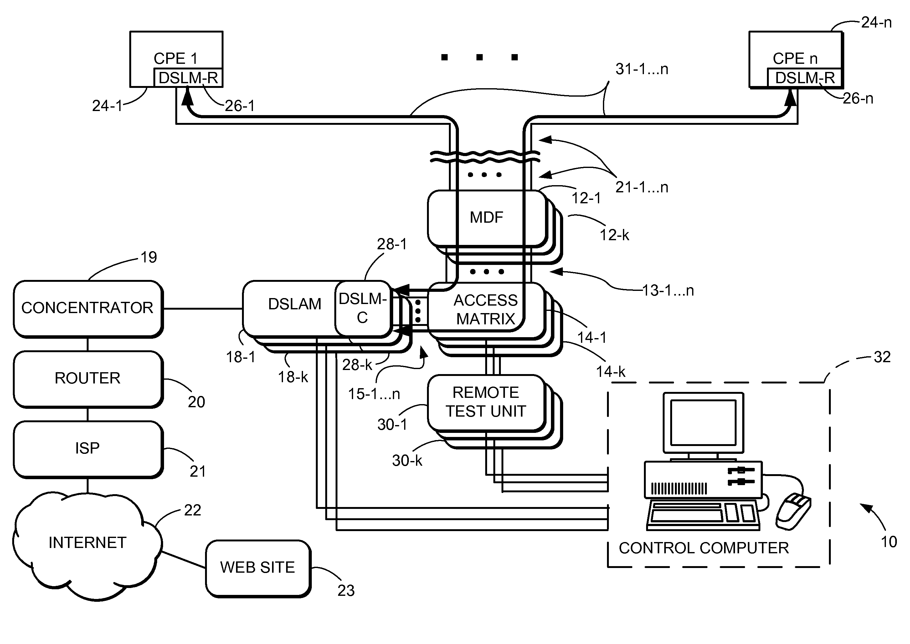
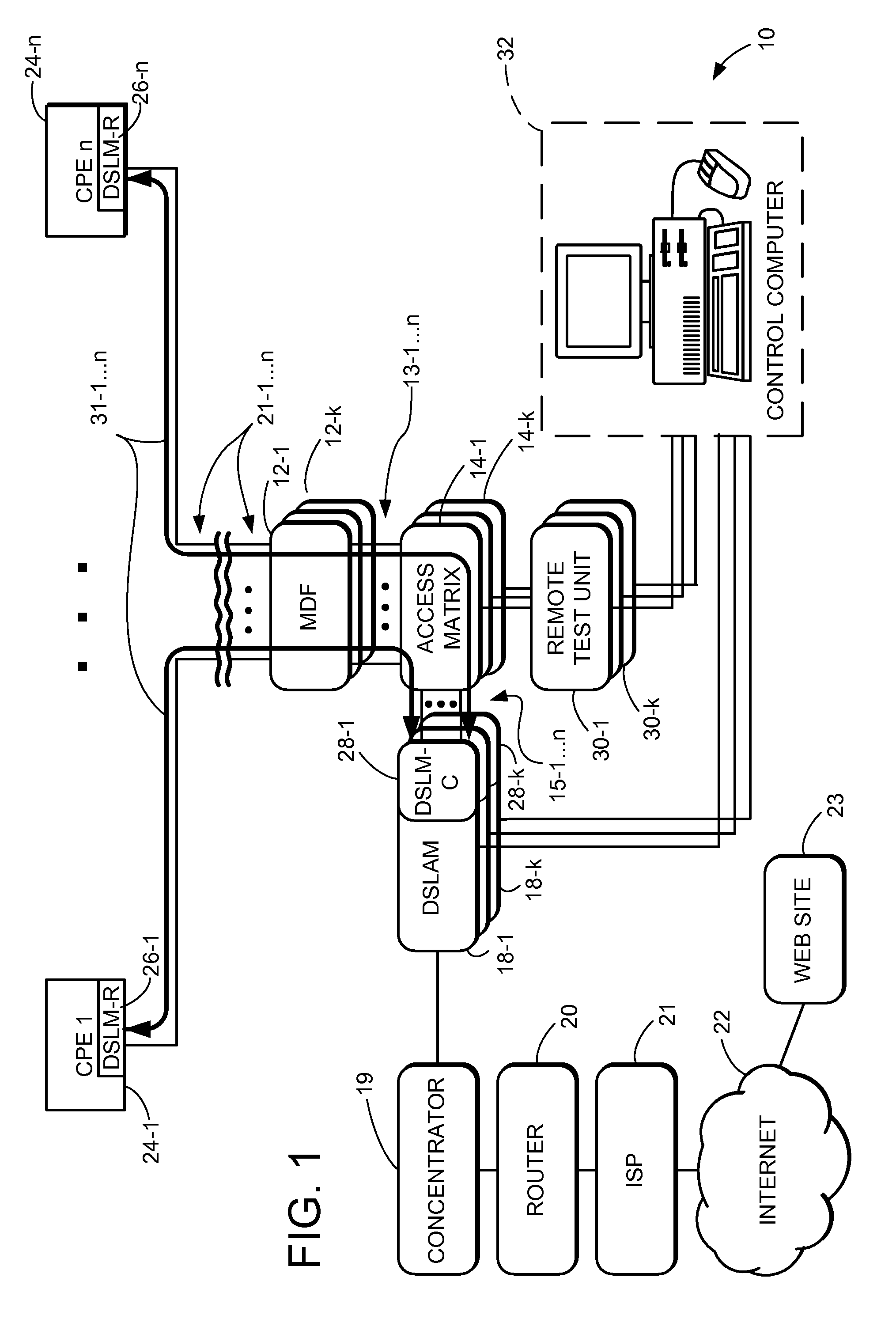
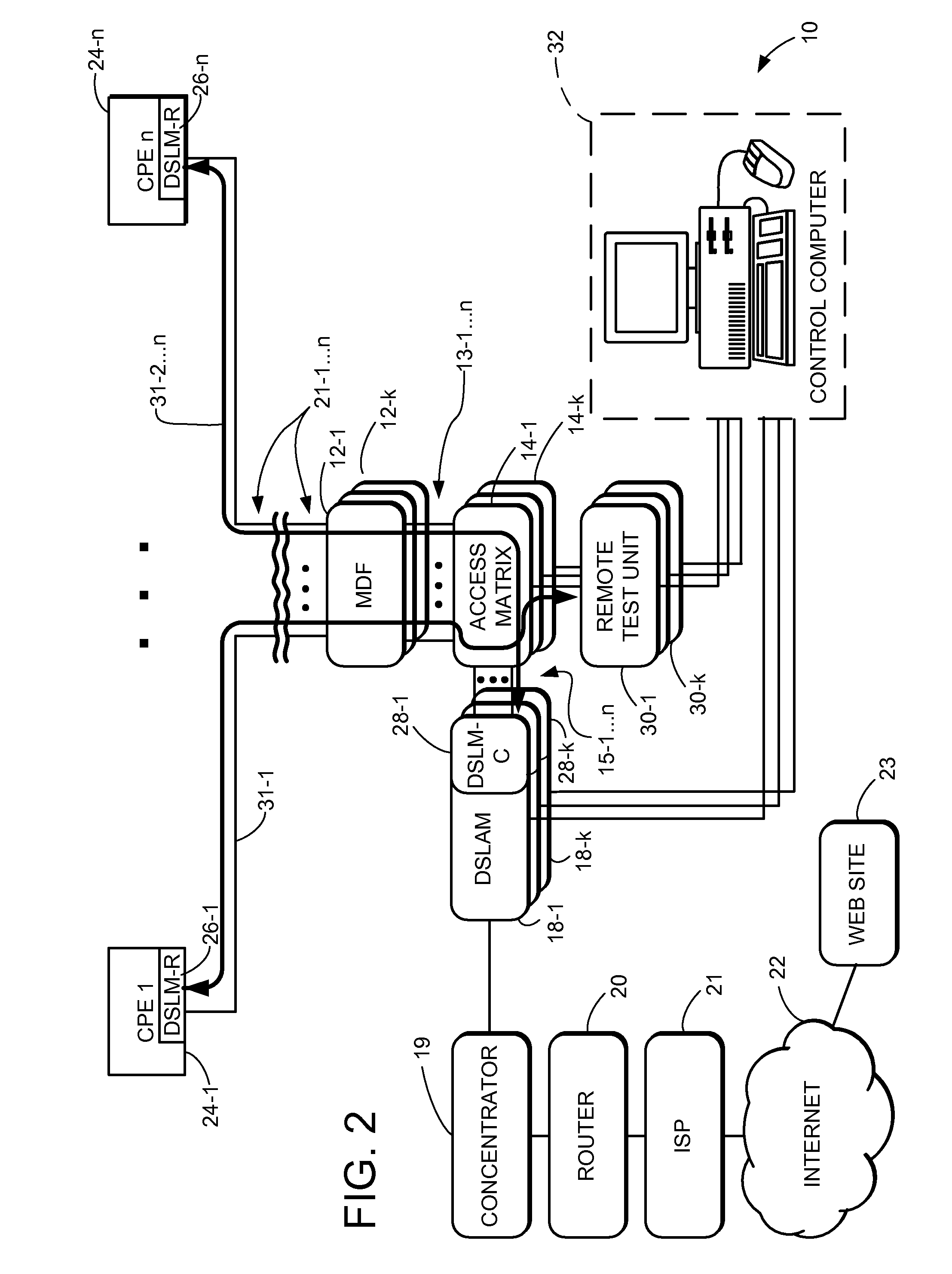
"The present invention provides a remote test unit (RTU) and method of operation that can emulate a central Digital Subscriber Line Module (DSLM-C) for testing customer premises equipment containing a remote Digital Subscriber Line Module (DSLM-R), and can also emulate a DSLM-R for testing central offices equipment including a DSLAM containing a DSLM-C. The RTU can further test, using emulation, layers of the Internet Protocol (IP) stack connected to the DSLM-C. The invention also provides a network that includes a plurality of customer premises equipment containing a DSLM-R and central offices equipment containing a DSLM-C, connected through an access matrix. The RTU can selectively connect the customer premises equipment to the DSLM-C or to the access matrix. The invention also provides a method for testing an ISO / OSI layer connected to a DSLM-C. The technical effects of the invention include improved testing efficiency and accuracy, as well as simplified and cost-effective network maintenance and troubleshooting."

Problems solved by technology

In the prior art configurations, when there is a non-operational connection between a CPE and the DSLAM in the central office, it is extremely difficult to determine if there is a defect in the CPE or in the DSLAM.
Another problem encountered with the prior art configurations is that there is no convenient way to facilitate upper layer testing.

Method used


Image

  • Remote test unit
  • Remote test unit
  • Remote test unit

Examples


Embodiment Construction

[0026] Referring now to Table 1, therein is shown the International Organization for Standardization Open Systems Interconnect (ISO / OSI) reference model.

TABLE 1Layer No.Layer NameFunctions1PhysicalHardware connection2Data linkTransmission of information3NetworkTransport routes, message handling andtransfer4TransportReliability of communication, service quality5SessionEstablishing, maintaining, and coordinatingcommunication6PresentationText formatting and display, code conversion7ApplicationProgram-to-program transfer of information

[0027] The ISO / OSI reference model is a layered architecture that standardizes levels of service and types of interaction for computers exchanging information through a communication network. The ISO / OSI reference model separates computer-to-computer communications into seven protocol layers, or levels, each building and relying upon the standards contained in the layers below it.

[0028] The physical layer is the first layer in the ISO / OSI reference mode...


PUM


Abstract

A remote test unit and method of operation are provided for utilizes the ability of an access matrix ability to route signals. The Remote Test Unit can emulate a central Digital Subscriber Line Modem (DSLM-C) for testing customer premises equipment containing a remote Digital Subscriber Line Modem (remote Digital Subscriber Line Modem). The Remote Test Unit can also emulate a remote Digital Subscriber Line Modem for testing central offices equipment including a digital subscriber line access multiplexer (DSLAM) containing a central Digital Subscriber Line Modem. The Remote Test Unit can also emulate a concentrator connected to the DSLAM, a router connected to the concentrator, an Internet service provider (ISP) connected to the router, and a web site connected to the Internet service provider over the Internet.

Description

CROSS-REFERENCE TO RELATED APPLICATIONS [0001] This application claims the benefit of U.S. Provisional patent application Ser. No. 60 / 279,351 filed Mar. 27, 2001. [0002] This is a continuation of co-pending U.S. patent application Ser. No. 10 / 029,662 filed Dec. 18, 2001. [0003] The present invention relates to, and incorporates by reference: 1) U.S. patent application Ser. No. 09 / 295,857, entitled “Detection of Bridge Tap Using Frequency Domain Analysis,” filed on Apr. 21, 1999, now U.S. Pat. No. 6,177,801; and 2) U.S. application Ser. No. 09 / 574,696, entitled “Digital Subscriber Line Access and Network Testing Multiplexer,” filed on May 17, 2000, now U.S. Pat. No. 6,434,221.TECHNICAL FIELD [0004] The present invention relates generally to communication networks, and more specifically to the testing of communication networks. BACKGROUND ART [0005] The demand for access to digital communications networks, such as the Internet, is directly related to the speed or rate at which such ne...

Claims


Application Information

Patent Timeline
Patent Type & Authority Applications(United States)
IPC IPC(8): H04M1/24H04M3/08H04M3/22
CPCH04L1/243H04M11/062
Inventor CHONG, RAYMOND L.
Owner VEEX
Learn More