
Unitized hydraulic system

a hydraulic system and hydraulic system technology, applied in the field of hydraulic systems, can solve the problems of increasing the complexity of the system, so as to achieve the effect of simple responsibilities and tasks, easy repair, and easy incorporation into the equipment design

Inactive Publication Date: 2007-05-31
LUDINGTON TECH INC
View PDF8 Cites 22 Cited by
  • Summary
  • Abstract
  • Description
  • Claims
  • Application Information

AI Technical Summary

Benefits of technology

[0010] As mentioned above, the present invention combines the necessary components to create a unitized system which has several advantages. Specifically, a single utilized system can be installed and utilized within a piece of equipment, as a single component. Further, the single hydraulic actuator, for performing some defined movement, can be designed into a system, without the overall need for coordinating components typically utilized. As a result, individual unitized hydraulic systems can easily be replaced and swapped, by simply removing the entire component and replacing as necessary.
[0015] As generally outlined above, it is an object of the present invention to provide a single hydraulic system which is virtually self-contained and capable of using incorporation into related equipment. Consequently, the equipment designer and maintenance personal have greatly simplified responsibilities and tasks and can concern themselves with other aspects of the equipment design.
[0016] It is a further object of the present invention to provide a hydraulic actuator system which is easily incorporated into an equipment design, and likewise easily repaired should any conditions exist.

Problems solved by technology

As can be appreciated, hydraulic systems range in complexity from very straightforward simple systems, to very complex.
Conversely, more complex systems such as the above-mentioned earth moving equipment involves multiple cylinders and multiple control components, all cooperating with one another to allow multiple components to be moved and positioned in desired ways.
As can be imagined, the use of these multiple hoses, along with all related fittings and coupling components, is not entirely desirable and increases the complexity of the system.
In addition to the hydraulic components mentioned above, corresponding electrical couplings and controls are often included, thus increasing the complexity of the system.
Due to the various concerns, however, this is often not possible or realistic.

Method used


Image

  • Unitized hydraulic system
  • Unitized hydraulic system
  • Unitized hydraulic system

Examples


Embodiment Construction

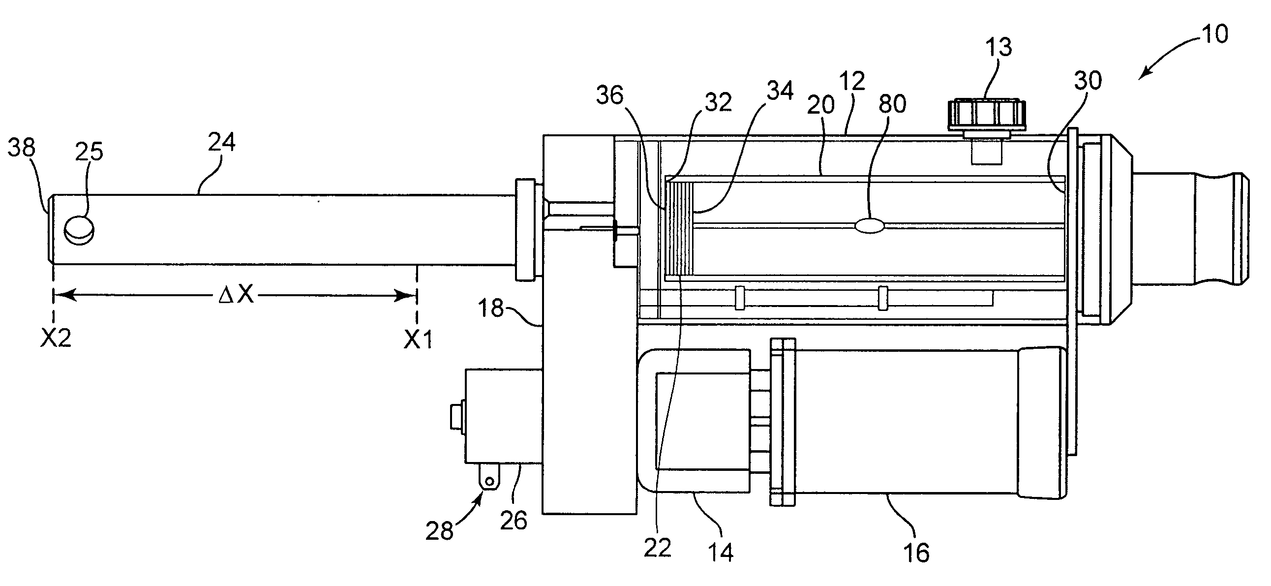
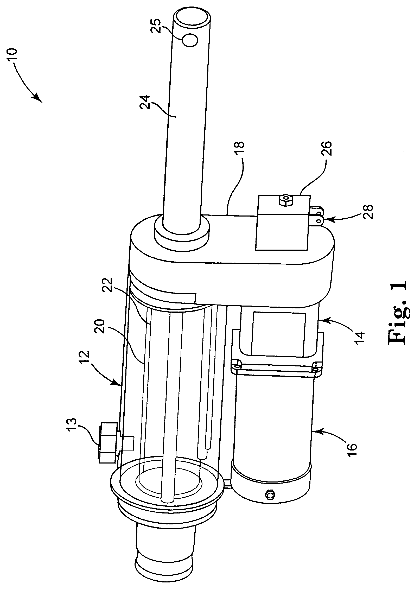
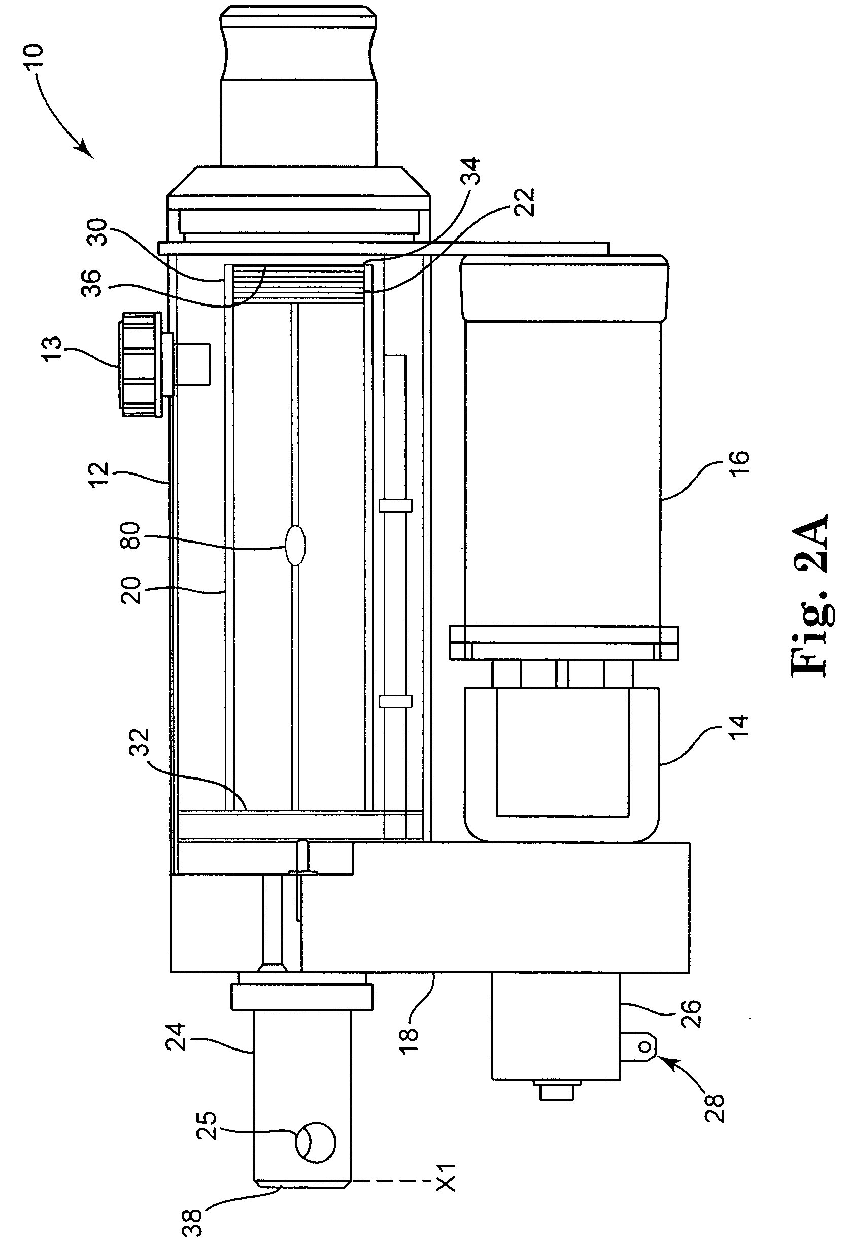
[0029] The present invention involves a unitized hydraulic system for use in multiple applications. As will be further described below, by combining multiple unitized hydraulic systems, many different device applications could be achieved. Each unitized hydraulic system may be entirely self-contained and may include, among other components, a motor, control electronics, a hydraulic pump, a hydraulic control valve, and a hydraulic cylinder. Furthermore, all fluid flow paths may be entirely self-contained within the unitized system, thus eliminating the need for hoses and complex valve bodies. Generally speaking, control of the unitized system may be achieved via electrical controls which actuate the motor in an appropriate way.

[0030]FIG. 1 is a perspective view of one embodiment of a unitized hydraulic system 10 according to the present invention, which includes tank 12, hydraulic pump 14, pump motor 16, control valve 18, and an actuator including hydraulic cylinder 20. In FIG. 1, t...


PUM


Abstract

A unitized hydraulic system comprises a tank for holding hydraulic fluid, a hydraulic pump powered by a pump motor for receiving hydraulic fluid from the tank and creating a high pressure stream of fluid, a control valve for receiving hydraulic fluid from the hydraulic pump and regulating movement of the hydraulic fluid within the system, an actuator for receiving hydraulic fluid from the control valve to drive a shaft coupled to the actuator, and a controller in communication with the pump motor and configured to provide controlled actuation of the pump motor, wherein all components are coupled together to form a single unit which is capable of being easily installed and interchanged.

Description

CROSS REFERENCE TO RELATED APPLICATIONS [0001] This application claims the benefit of U.S. Provisional Patent Application Ser. No. 60 / 736,218, filed Nov. 14, 2005, the entirety of which is incorporated by reference.BACKGROUND OF THE INVENTION [0002] Generally speaking, the present invention relates to hydraulic systems. More specifically, the present invention relates to a unitized hydraulic system which can be used as a single component of another device or system. [0003] Hydraulic systems are widely used for a number of applications in today's society. Most of these hydraulic systems are utilized in different mechanical devices, which are used for many different applications. For example, manufacturing equipment typically uses hydraulic systems to operate certain manufacturing processes. Further, construction and earth moving equipment (bulldozers, front end loaders, graders, etc.) all utilize hydraulic systems to actuate and move various components. As another example, snowplows ...

Claims


Application Information

Patent Timeline
IPC IPC(8): F16D31/02
CPCF15B1/26F15B15/18
Inventor MENZE, PETER C.
Owner LUDINGTON TECH INC
Learn More