
Battery monitor

a technology of power consumption monitoring and battery life, which is applied in the field of power consumption monitoring circuitry, can solve the problems of many other tags still having a long life and it is difficult to estimate the battery life of a tag, so as to accurately determine how much energy has been consumed and not to significantly shorten the battery life of the tag

Inactive Publication Date: 2007-05-24
STRAGENT
View PDF15 Cites 23 Cited by
  • Summary
  • Abstract
  • Description
  • Claims
  • Application Information

AI Technical Summary

Benefits of technology

This solution enables accurate estimation of battery life, reducing unnecessary replacements and extending the operational life of RFID tags by monitoring power usage across various states, ensuring efficient battery management.

Problems solved by technology

Because certain tags are active more often than others, it is hard to estimate the battery life of a tag.
However, many other tags may still have a long life remaining.

Method used


Image

  • Battery monitor
  • Battery monitor
  • Battery monitor

Examples


Embodiment Construction

[0050] The following description is the best embodiment presently contemplated for carrying out the present invention. This description is made for the purpose of illustrating the general principles of the present invention and is not meant to limit the inventive concepts claimed herein.

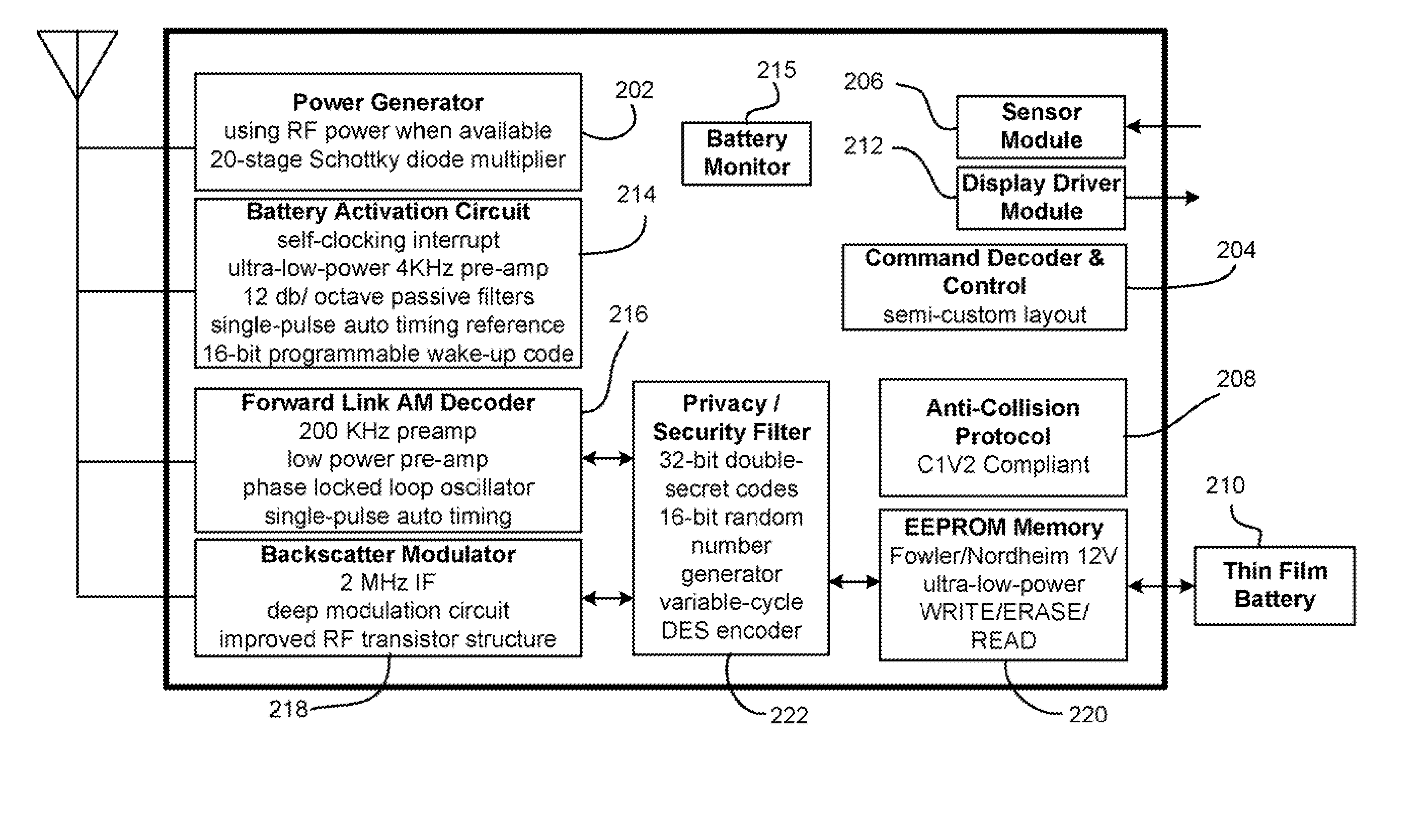
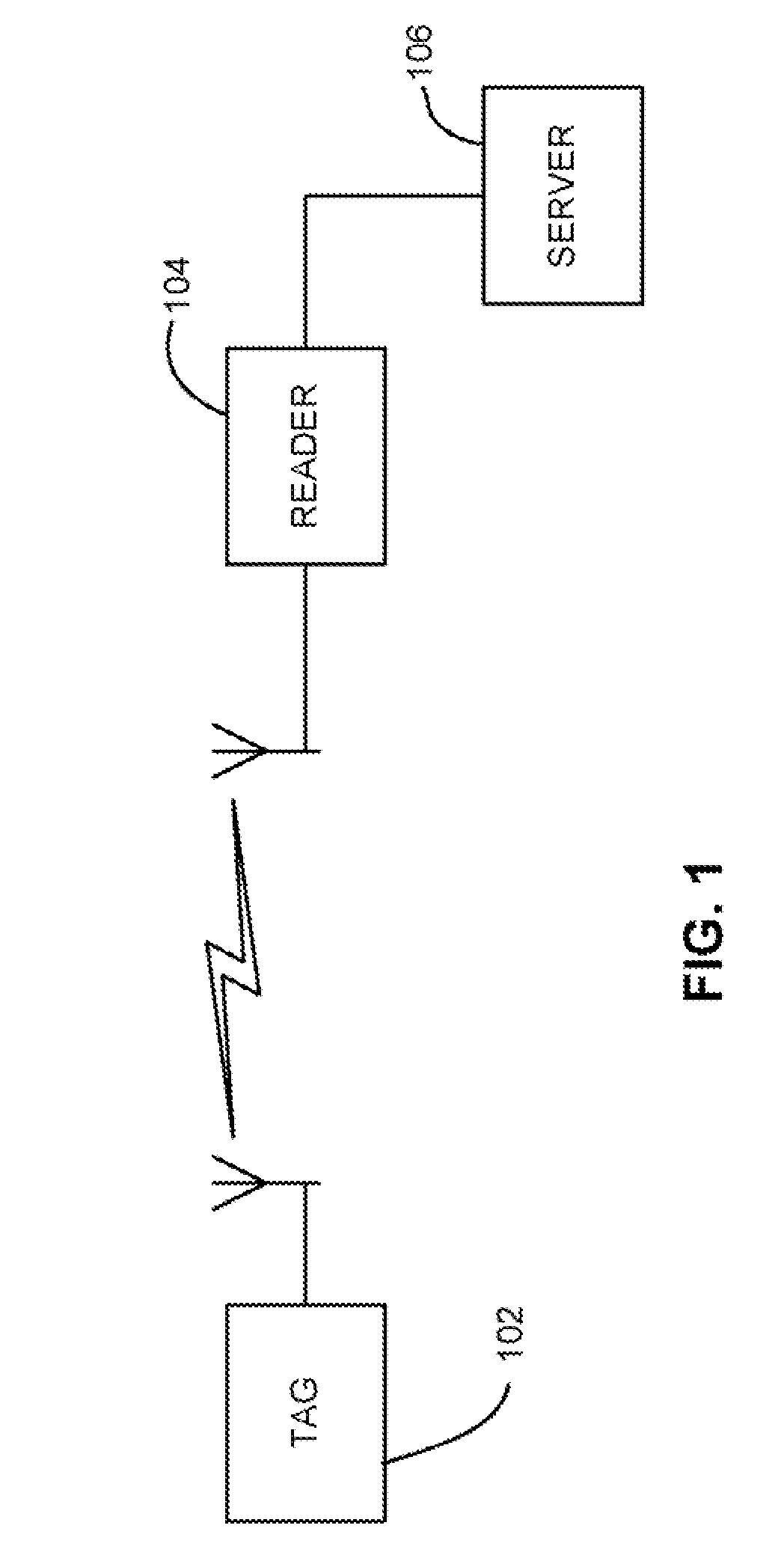
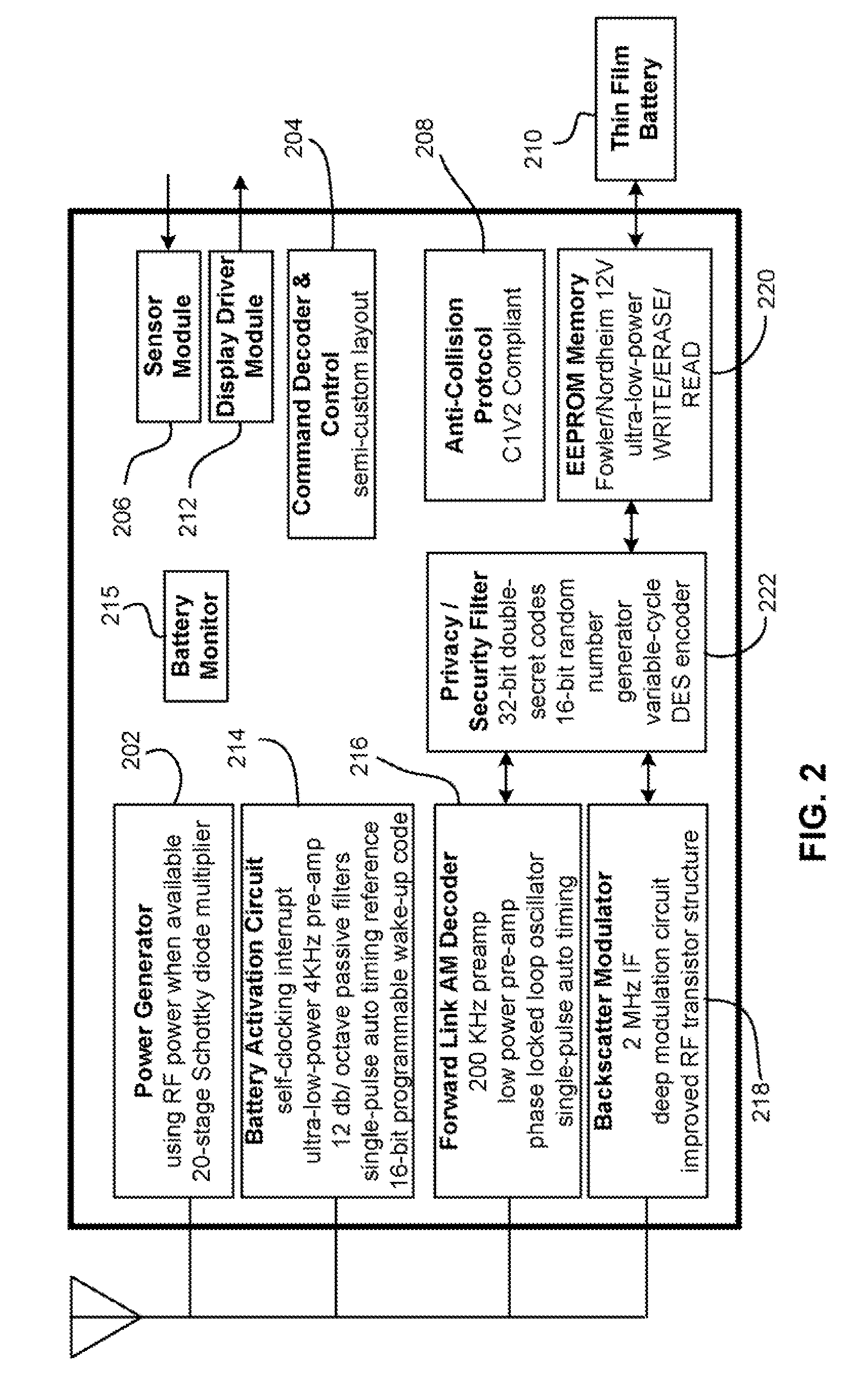
[0051] The following specification describes systems and methods for tracking the total amount of time that a host device spends in a high-power “Active” state and optionally, low-power state(s), to thereby allow estimation of the total power consumed by the host device. Active states can include those states where the device is actively using power, or where power consumption is above what would be considered a low-power state. Note that the host device can have multiple active states, and operation of the system can vary for each active state. Low power states typically include “hibernate”, “idle”, or “wait / listen for an activation command” states. A remote device can query the device to accuratel...


PUM


Abstract

Circuit and methods for tracking the total amount of time that a host device has spent in its high power “activated” state (and optionally idle and hibernate states) and thereby can estimate the total power consumed by the host device. A value representing this time may be send to a remote device to, for example, accurately determine how much of the energy has been consumed by the host device and how much time is left and / or how many operations can be performed before the host device's battery is exhausted.

Description

RELATED APPLICATIONS [0001] This application is a continuation of U.S. patent application Ser. No. 11 / 124,487, filed May 6, 2005. The present application is also related to U.S. patent application Ser. No. 11 / 124,485, entitled “ACCURATE PERSlSTENT MODES” and filed May 6, 2005, and which is incorporated by reference.FIELD OF THE INVENTION [0002] The present invention relates to power consumption monitoring circuitry, and more particularly, this invention relates to circuits that monitor power consumption in a host device. BACKGROUND OF THE INVENTION [0003] Radio Frequency Identification (RFID) technology employs a radio frequency (“RF”) wireless link and ultra-small embedded computer circuitry. RFID technology allows physical objects to be identified and tracked via these wireless “tags”. It functions like a bar code that communicates to the reader automatically without requiring manual line-of-sight scanning or singulation of the objects. RFID promises to radically transform the ret...

Claims


Application Information

Patent Timeline
Patent Type & Authority Applications(United States)
IPC IPC(8): G01R31/36G06F19/00
CPCG01R31/36G06K7/0008G06K19/0707G06K19/0712G06K19/0723
Inventor STEWART, ROGER GREEN
Owner STRAGENT
Learn More